
Page 245 - Complete Wireless Design
P. 245
Oscillator Design
244 Chapter Four
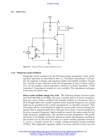
Figure 4.25 A type of Pierce crystal oscillator circuit.
4.3.3 Designing crystal oscillators
Designing crystal oscillators by the following design procedures, while verify-
ing their operation as described in Sec. 4.1, “Oscillator Simulation,” will per-
mit the engineer to design and construct stable and reliable oscillator circuits
for a variety of uses. Because of the low frequencies of some of these oscilla-
tors, we can employ a Spice simulator—instead of a linear simulator—if the
transistor’s S-parameter models are not available. The simulation technique
is the same for either case.
Pierce crystal oscillator design (Fig. 4.26). The following design functions quite
well from 600 kHz to 30 MHz, and uses a crystal that is in series resonance.
However, since a Pierce oscillator will actually oscillate at a frequency that is
20 to 50 ppm above the crystal’s marked series resonant frequency, the crystal
itself can be specified to the crystal manufacturer as “parallel resonant.” This
will simply tell the manufacturer to build the crystal with a series resonant fre-
quency that is approximately 90 to 100 ppm lower than a crystal specified at
its series resonant frequency (both crystals are exactly the same except for this
slight frequency modification). The parallel resonant designation will permit
the Pierce to be slightly tweaked to operate at exactly the frequency marked on
the crystal’s can by the mere inclusion of a small variable capacitor shown as
C [or by a varactor circuit for a simple voltage-controlled crystal oscillator
3
(VCXO)]. This adjustable capacitor, which is in series with the crystal, can also
Downloaded from Digital Engineering Library @ McGraw-Hill (www.digitalengineeringlibrary.com)
Copyright © 2004 The McGraw-Hill Companies. All rights reserved.
Any use is subject to the Terms of Use as given at the website.