
Page 319 - Complete Wireless Design
P. 319
Mixer Design
318 Chapter Seven
Single-balanced mixers are a different story. The distributed passive single-
balanced mixer presented next will be lower in cost to personally design and
build than to purchase—depending on, of course, the quantities involved.
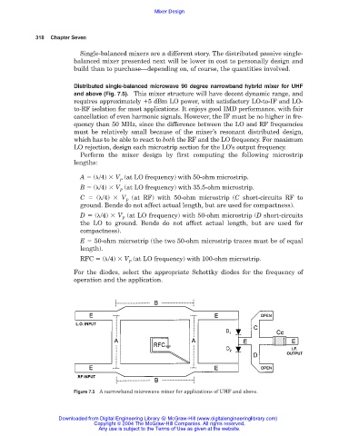
Distributed single-balanced microwave 90 degree narrowband hybrid mixer for UHF
and above (Fig. 7.5). This mixer structure will have decent dynamic range, and
requires approximately 5 dBm LO power, with satisfactory LO-to-IF and LO-
to-RF isolation for most applications. It enjoys good IMD performance, with fair
cancellation of even harmonic signals. However, the IF must be no higher in fre-
quency than 50 MHz, since the difference between the LO and RF frequencies
must be relatively small because of the mixer’s resonant distributed design,
which has to be able to react to both the RF and the LO frequency. For maximum
LO rejection, design each microstrip section for the LO’s output frequency.
Perform the mixer design by first computing the following microstrip
lengths:
A ( /4) V (at LO frequency) with 50-ohm microstrip.
P
B ( /4) V (at LO frequency) with 35.5-ohm microstrip.
P
C ( /4) V (at RF) with 50-ohm microstrip (C short-circuits RF to
P
ground. Bends do not affect actual length, but are used for compactness).
D ( /4) V (at LO frequency) with 50-ohm microstrip (D short-circuits
P
the LO to ground. Bends do not affect actual length, but are used for
compactness).
E 50-ohm microstrip (the two 50-ohm microstrip traces must be of equal
length).
RFC ( /4) V (at LO frequency) with 100-ohm microstrip.
P
For the diodes, select the appropriate Schottky diodes for the frequency of
operation and the application.
Figure 7.5 A narrowband microwave mixer for applications of UHF and above.
Downloaded from Digital Engineering Library @ McGraw-Hill (www.digitalengineeringlibrary.com)
Copyright © 2004 The McGraw-Hill Companies. All rights reserved.
Any use is subject to the Terms of Use as given at the website.