
Page 323 - Complete Wireless Design
P. 323
Mixer Design
322 Chapter Seven
frequency IF output signal should be sent out of the mixer’s RF port. This is
also valid for transmitter design, since the mixer will also be performing up-
conversion.
When viewing the mixer’s input intercept point (IIP) specification on a data
sheet [IIP is equal to the input RF power level, in dBm, in which the attenua-
tion of intermodulation distortion will be at 0 dBc (0 dB below the carrier)], we
sometimes may be required to convert from the input intercept to an output
intercept point (OIP). This can be accomplished by:
OIP IIP CL
where OIP mixer output intercept point, dBm
IIP mixer input intercept point, dBm
CL mixer conversion loss (usually 6 to 9 dB), dB
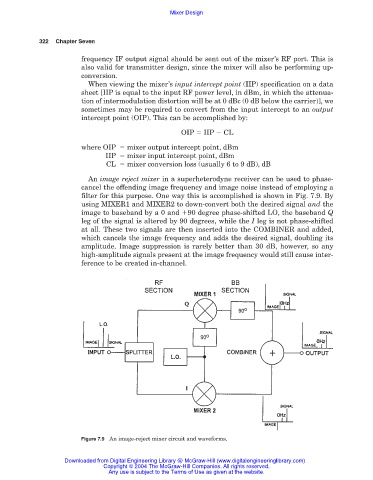
An image reject mixer in a superheterodyne receiver can be used to phase-
cancel the offending image frequency and image noise instead of employing a
filter for this purpose. One way this is accomplished is shown in Fig. 7.9. By
using MIXER1 and MIXER2 to down-convert both the desired signal and the
image to baseband by a 0 and 90 degree phase-shifted LO, the baseband Q
leg of the signal is altered by 90 degrees, while the I leg is not phase-shifted
at all. These two signals are then inserted into the COMBINER and added,
which cancels the image frequency and adds the desired signal, doubling its
amplitude. Image suppression is rarely better than 30 dB, however, so any
high-amplitude signals present at the image frequency would still cause inter-
ference to be created in-channel.
Figure 7.9 An image-reject mixer circuit and waveforms.
Downloaded from Digital Engineering Library @ McGraw-Hill (www.digitalengineeringlibrary.com)
Copyright © 2004 The McGraw-Hill Companies. All rights reserved.
Any use is subject to the Terms of Use as given at the website.