
Page 321 - Complete Wireless Design
P. 321
Mixer Design
320 Chapter Seven
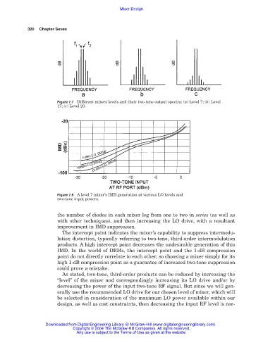
Figure 7.7 Different mixers levels and their two-tone output spectra: (a) Level 7; (b) Level
17; (c) Level 23.
Figure 7.8 A level 7 mixer’s IMD generation at various LO levels and
two-tone input powers.
the number of diodes in each mixer leg from one to two in series (as well as
with other techniques), and then increasing the LO drive, with a resultant
improvement in IMD suppression.
The intercept point indicates the mixer’s capability to suppress intermodu-
lation distortion, typically referring to two-tone, third-order intermodulation
products. A high intercept point decreases the undesirable generation of this
IMD. In the world of DBMs, the intercept point and the 1-dB compression
point do not directly correlate to each other; so choosing a mixer simply for its
high 1-dB compression point as a guarantee of increased two-tone suppression
could prove a mistake.
As stated, two-tone, third-order products can be reduced by increasing the
“level” of the mixer and correspondingly increasing its LO drive and/or by
decreasing the power of the input two-tone RF signal. But since we will gen-
erally use the recommended LO drive for our chosen level of mixer, which will
be selected in consideration of the maximum LO power available within our
design, as well as cost constraints, then decreasing the input RF level is nor-
Downloaded from Digital Engineering Library @ McGraw-Hill (www.digitalengineeringlibrary.com)
Copyright © 2004 The McGraw-Hill Companies. All rights reserved.
Any use is subject to the Terms of Use as given at the website.