
Page 394 - Complete Wireless Design
P. 394
Communications System Design
Communications System Design 393
from the first mixer from reentering its output port. Moreover, the IF AMP will
provide a relatively decent 50-ohm termination for the IF BPF at the mixer
port because most mixers, because of their continuous switching action, have
difficulty maintaining anything close to 50 j0 ohms. The first mixer converts
the low input signal up to the IF, while the LO BPF filters wideband noise,
harmonics, and spurs created by the LO and/or its LO AMP. The fixed LO is a
high-Q, and thus low-phase-noise and high-stability, crystal oscillator. The
BPF and/or the AMP may or may not be present, depending on the modulation
source and its requirements (usually a modem in commercial data communi-
cations equipment, or an I/Q modulator).
The transmitter’s output may also be tapped by a directional coupler in
order to feed the signal’s amplitude information to a microprocessor to main-
tain proper transmitted output levels by an automatic level control (ALC) cir-
cuit. A temperature sensor and reverse power level signals may also be output
to a controller to prevent SSPA damage or destruction.
The PA stage of a digital transmitter should have an SNR of greater than 65
dBc so as not to degrade the overall system’s signal-to-noise ratio, while the phase
noise of the LOs should be better than 95 dB/Hz at 10 kHz for a typical QAM
transmitter. The digital transmitter’s IF and RF filters should also pass the entire
signal with no passband cutting, with an amplitude tilt of less than 2 dB, and with
in-band ripple of less than ±0.5 dB. Spurious signal outputs into adjacent chan-
nels will normally need to be better than 65 dBc in most of the radio services.
9.3 Link Budgets
9.3.1 Introduction
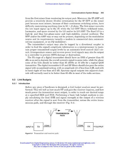
Before any piece of hardware is designed, a link budget analysis must be per-
formed. This will tell us how much NF and gain the receiver requires, and how
much power the transmitter must output, in order to reach our desired range
at a specified BER and SNR. Performing a basic link budget analysis is sim-
ply calculating the final SNR and signal strength at the output of a wireless
receiver after the signal is sent from the transmitter, across the entire trans-
mission path, and through the receiver (Fig. 9.4).
Figure 9.4 Transmitter and receiver path.
Downloaded from Digital Engineering Library @ McGraw-Hill (www.digitalengineeringlibrary.com)
Copyright © 2004 The McGraw-Hill Companies. All rights reserved.
Any use is subject to the Terms of Use as given at the website.