Page 397 - Complete Wireless Design
P. 397

Communications System Design


            396  Chapter Nine

                                 P   power, in dBm, delivered by the transmitter into its own
                                  t
                                      antenna
                                 G   gain, in dB, of the transmitter’s antenna
                                  t
                                 G   gain, in dB, of the receiver’s antenna
                                  r
                              PL      free-space path loss, in dB, between the transmitter and
                                 dB
                                      receiver antennas
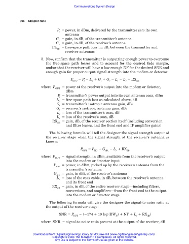
                        5. Now, confirm that the transmitter is outputting enough power to overcome
                           the free-space path losses and to account for the desired fade margin,
                           and/or that the receiver will have a low enough NF for the desired SNR and
                           enough gain for proper output signal strength into the modem or detector:
                                         P     P   L   G   G   L   L   RX
                                          OUT   t    p    t    r   t    r     dB
                        where P       power at the receiver’s output into the modem or detector,
                                OUT
                                      dBm
                                  P   transmitter’s power output into its own antenna coax, dBm
                                   t
                                 L   free-space path loss as calculated above, dB
                                  p
                                 G   transmitter’s isotropic antenna gain, dBi
                                   t
                                 G   receiver’s isotropic antenna gain, dBi
                                  r
                                 L   loss of the transmitter’s coax, dB
                                   t
                                 L   loss of the receiver’s coax, dB
                                  r
                               RX     gain, dB, of the receiver section itself (including conversion
                                 dB
                                      and filter losses, and the front end and IF amplifier gains)
                             The following formula will tell the designer the signal strength output of
                           the receiver stage when the signal strength at the receiver’s antenna is
                           known:
                                              P      P     G     L   RX
                                               OUT    SIG   dB;   r     dB
                        where P       signal strength, in dBm, available from the receiver’s output
                                OUT
                                      into the modem or detector input
                               P      power, in dBm, picked up by the receiver’s antenna from the
                                 SIG
                                      transmitter’s antenna
                               G      gain, in dBi, of the receiver’s antenna
                                 dBi
                                 L   loss of the coax cable, in dB, between the receiver’s antenna
                                  r
                                      and its front end
                              RX      gain, in dB, of the entire receiver stage—including filters,
                                 dB
                                      conversions, and amplifiers—from the front end to the output
                                      into the modem or detector stage
                             The following formula will give the designer the signal-to-noise ratio at
                           the output of the receiver stage:
                                  SNR   P       ( 174   10 log (BW )   NF   L   RX )
                                          OUT                     N           r     dB
                        where SNR   signal-to-noise ratio present at the output of the receiver, dB


                   Downloaded from Digital Engineering Library @ McGraw-Hill (www.digitalengineeringlibrary.com)
                               Copyright © 2004 The McGraw-Hill Companies. All rights reserved.
                                Any use is subject to the Terms of Use as given at the website.
   392   393   394   395   396   397   398   399   400   401   402