
Page 399 - Complete Wireless Design
P. 399
Communications System Design
398 Chapter Nine
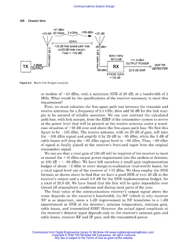
Figure 9.5 Basic link budget analysis.
or modem of 10 dBm, with a minimum SNR of 20 dB, at a bandwidth of 1
MHz. What would be the specifications of the receiver necessary to meet this
requirement?
First, we must calculate the free-space path loss between the transmit and
receive antennas for a frequency of 2.4 GHz, then add 20 dB for the link mar-
gin to be assured of reliable operation. We can now subtract the calculated
path loss, with link margin, from the EIRP of the transmitter system to arrive
at the power level that will be present at the receive antenna under a worst-
case situation of 20 dB over and above the free-space path loss. We find this
figure to be 105 dBm. The receive antenna, with its 20 dB of gain, will take
the 105 dBm signal and amplify it by 20 dB to 85 dBm, while the 3 dB of
cable losses will drop the 85 dBm signal level to 88 dBm. Thus, 88 dBm
of signal is finally placed at the receiver’s front-end input from the original
transmitter signal.
We can see that a total gain of 100 dB will be required of the receiver to meet
or exceed the 10 dBm output power requirement into the modem or detector,
or 100 dB ( 88 dBm). We have left ourselves a small gain implementation
budget of about 2 dBm to cover design-to-realization (real-world) losses, for
a total signal level out of the receiver of 12 dBm. We then employ the SNR
formula as shown above to find that we have a good SNR of over 20 dB at the
receiver’s output and a small 0.9 dB for the SNR implementation budget, for
a total of 20.9 dB. We have found that the link will be quite dependable over
almost all atmospheric conditions and during most parts of the year.
The final value of the communications receiver’s output signal above the
noise depends on the receiver’s bandwidth, its NF (which is why receiver
NF is so important, since a 1-dB improvement in NF translates to a 1-dB
improvement in SNR at the detector), antenna temperature, antenna gain,
cable losses, and transmitted EIRP. However, the actual signal amplitude at
the receiver’s detector input depends only on the receiver’s antenna gain and
cable losses, receiver RF and IF gain, and the transmitted power.
Downloaded from Digital Engineering Library @ McGraw-Hill (www.digitalengineeringlibrary.com)
Copyright © 2004 The McGraw-Hill Companies. All rights reserved.
Any use is subject to the Terms of Use as given at the website.