
Page 440 - Complete Wireless Design
P. 440
Wireless Issues
Wireless Issues 439
antenna performance because smaller lobes collect less temperature, and thus
less noise, from the earth.
10.8.2 Common antenna types
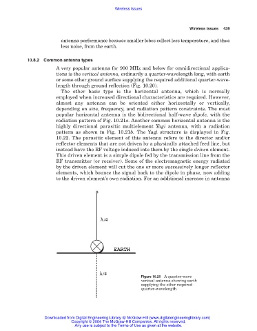
A very popular antenna for 900 MHz and below for omnidirectional applica-
tions is the vertical antenna, ordinarily a quarter-wavelength long, with earth
or some other ground surface supplying the required additional quarter-wave-
length through ground reflection (Fig. 10.20).
The other basic type is the horizontal antenna, which is normally
employed when increased directional characteristics are required. However,
almost any antenna can be oriented either horizontally or vertically,
depending on size, frequency, and radiation pattern constraints. The most
popular horizontal antenna is the bidirectional half-wave dipole, with the
radiation pattern of Fig. 10.21a. Another common horizontal antenna is the
highly directional parasitic multielement Yagi antenna, with a radiation
pattern as shown in Fig. 10.21b. The Yagi structure is displayed in Fig.
10.22. The parasitic element of this antenna refers to the director and/or
reflector elements that are not driven by a physically attached feed line, but
instead have the RF voltage induced into them by the single driven element.
This driven element is a simple dipole fed by the transmission line from the
RF transmitter (or receiver). Some of the electromagnetic energy radiated
by the driven element will cut the one or more successively longer reflector
elements, which bounce the signal back to the dipole in phase, now adding
to the driven element’s own radiation. For an additional increase in antenna
Figure 10.20 A quarter-wave
vertical antenna showing earth
supplying the other required
quarter-wavelength.
Downloaded from Digital Engineering Library @ McGraw-Hill (www.digitalengineeringlibrary.com)
Copyright © 2004 The McGraw-Hill Companies. All rights reserved.
Any use is subject to the Terms of Use as given at the website.