
Page 437 - Complete Wireless Design
P. 437
Wireless Issues
436 Chapter Ten
Verify that your parts supplier is dependable, since not all components or
RFICs that are in the data books will be truly available—either because they
are preliminary or because they have been discontinued.
Establish that every trace on the PCB is correctly routed, not only to make
sure it reaches the proper board location, but also to avoid unpleasant
coupling effects and EMI.
Validate that all active devices are soldered to the correct terminals
(especially diodes) and that all electrolytics are inserted with the proper
polarity.
Ascertain that components are of the appropriate value, and that they are
correctly and neatly soldered.
All of the above should be performed before turning on the prototype for the
first time to avoid an expensive, embarrassing, and time-consuming ending to
the infamous “smoke test.”
10.8 Antennas
10.8.1 Introduction
Antennas are designed to efficiently transform alternating current into elec-
tromagnetic waves, and to then send these waves out into free space. The elec-
tromagnetic waves are then caught by the receiving antenna, where they are
converted into an alternating current. The actual design of the antenna
depends on the frequency of its operation, output power, directivity, robust-
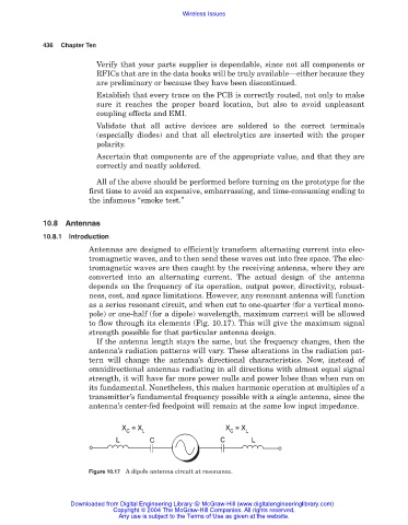
ness, cost, and space limitations. However, any resonant antenna will function
as a series resonant circuit, and when cut to one-quarter (for a vertical mono-
pole) or one-half (for a dipole) wavelength, maximum current will be allowed
to flow through its elements (Fig. 10.17). This will give the maximum signal
strength possible for that particular antenna design.
If the antenna length stays the same, but the frequency changes, then the
antenna’s radiation patterns will vary. These alterations in the radiation pat-
tern will change the antenna’s directional characteristics. Now, instead of
omnidirectional antennas radiating in all directions with almost equal signal
strength, it will have far more power nulls and power lobes than when run on
its fundamental. Nonetheless, this makes harmonic operation at multiples of a
transmitter’s fundamental frequency possible with a single antenna, since the
antenna’s center-fed feedpoint will remain at the same low input impedance.
Figure 10.17 A dipole antenna circuit at resonance.
Downloaded from Digital Engineering Library @ McGraw-Hill (www.digitalengineeringlibrary.com)
Copyright © 2004 The McGraw-Hill Companies. All rights reserved.
Any use is subject to the Terms of Use as given at the website.