
Page 441 - Complete Wireless Design
P. 441
Wireless Issues
440 Chapter Ten
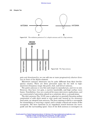
Figure 10.21 The radiation patterns of (a) a dipole antenna and (b) a Yagi antenna.
Figure 10.22 The Yagi antenna.
gain and directionality, we can add one or more progressively shorter direc-
tors in front of the dipole element.
Microwave antenna structures can be quite different from their low-fre-
quency cousins. There are three prevalent types for the mid- to high-
microwave-frequency range: the patch, dish, and helical antenna.
The patch antenna is very flat and simple to manufacture, and low in cost.
However, they have low gain, a narrow bandwidth, and high surface wave
losses. Nonetheless, they are a natural for many microwave applications, and
are constructed of microstrip placed on a substrate above a ground plane.
The dish antenna (Fig. 10.23) uses a spherical or parabolic focusing surface
constructed of solid sheet metal or wire mesh and, located at the antenna’s
focal point, an integral horn antenna. The horn antenna is fed by a waveguide
for transmitting or receiving a signal, and is simply a flared-out section of the
waveguide. The horn functions as an impedance match between the wave-
guide and the surrounding space. Gain of the dish antenna is contingent on
Downloaded from Digital Engineering Library @ McGraw-Hill (www.digitalengineeringlibrary.com)
Copyright © 2004 The McGraw-Hill Companies. All rights reserved.
Any use is subject to the Terms of Use as given at the website.