
Page 455 - Complete Wireless Design
P. 455
Wireless Issues
454 Chapter Ten
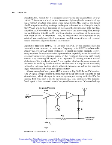
standard AGC circuit, but it is designed to operate on the transmitter’s IF (Fig.
10.28). This automatic level control decreases high-amplitude transmitted sig-
nals, without affecting nominal or lower signal levels. ALC controls the gain of
the IF stages by sending a voltage to the gate or base of a variable-gain ampli-
fier (VGA), which then decreases or increases the input power into the final
amplifier. ALC does this by tapping the output of the power amplifier, rectify-
ing and filtering this RF to DC, and then placing this voltage at the gain con-
trol input of the IF amplifiers. Thus, no matter what the amplitude of the
original baseband signal, the linear power amplifier cannot be overdriven and
create excessive adjacent channel interference.
Automatic frequency control. In low-cost non-PLL or non-crystal-controlled
transmitters or receivers, an automatic frequency control (AFC) can be used to
steady the system’s LC local oscillators. General frequency stability is obvi-
ously required for any superheterodyne receiver, especially when internal and
external temperature changes occur, or the resultant frequency drift would
convert any incoming RF signal to an improper IF, causing attenuation and
distortion of the baseband signal. A transmitter also has the same reasons to
maintain its stability for the receiver, and because it is capable of interfering
with other wireless devices within adjacent channels, as well as the negative
legal ramifications of a wandering transmitter.
A basic example of one type of AFC is shown in Fig. 10.29 for an FM receiver.
The IF signal is tapped from the last stage of the IF strip and sent into an FM
demodulator, which changes its own voltage output in step with the IF’s fre-
quency drift. This drift is due to the unstable LC local oscillators. The demodu-
lated signal is then inserted into the low-pass filter to obtain a DC control voltage
Figure 10.28 A transmitter’s ALC circuit.
Downloaded from Digital Engineering Library @ McGraw-Hill (www.digitalengineeringlibrary.com)
Copyright © 2004 The McGraw-Hill Companies. All rights reserved.
Any use is subject to the Terms of Use as given at the website.