
Page 457 - Complete Wireless Design
P. 457
Wireless Issues
456 Chapter Ten
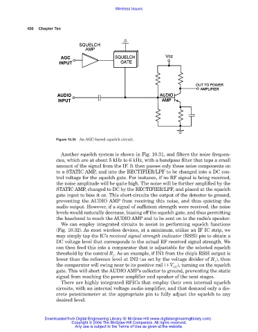
Figure 10.30 An AGC-based squelch circuit.
Another squelch system is shown in Fig. 10.31, and filters the noise frequen-
cies, which are at about 5 kHz to 6 kHz, with a bandpass filter that taps a small
amount of the signal from the IF. It then passes only these noise components on
to a STATIC AMP, and into the RECTIFIER/LPF to be changed into a DC con-
trol voltage for the squelch gate. For instance, if no RF signal is being received,
the noise amplitude will be quite high. The noise will be further amplified by the
STATIC AMP, changed to DC by the RECTIFIER/LPF, and placed at the squelch
gate input to bias it on. This short-circuits the output of the detector to ground,
preventing the AUDIO AMP from receiving this noise, and thus quieting the
audio output. However, if a signal of sufficient strength were received, the noise
levels would naturally decrease, biasing off the squelch gate, and thus permitting
the baseband to reach the AUDIO AMP and to be sent on to the radio’s speaker.
We can employ integrated circuits to assist in performing squelch functions
(Fig. 10.32). As most wireless devices, at a minimum, utilize an IF IC strip, we
may simply tap the IC’s received signal strength indicator (RSSI) pin to obtain a
DC voltage level that corresponds to the actual RF received signal strength. We
can then feed this into a comparator that is adjustable for the selected squelch
threshold by the control R . As an example, if IN1 from the chip’s RSSI output is
1
lower than the reference level at IN2 (as set by the voltage divider of R ), then
1
the comparator will swing near to its positive rail ( V ), turning on the squelch
CC
gate. This will short the AUDIO AMP’s collector to ground, preventing the static
signal from reaching the power amplifier and speaker of the next stages.
There are highly integrated RFICs that employ their own internal squelch
circuits, with an internal voltage audio amplifier, and that demand only a dis-
crete potentiometer at the appropriate pin to fully adjust the squelch to any
desired level.
Downloaded from Digital Engineering Library @ McGraw-Hill (www.digitalengineeringlibrary.com)
Copyright © 2004 The McGraw-Hill Companies. All rights reserved.
Any use is subject to the Terms of Use as given at the website.