
Page 133 - Compression Machinery for Oil and Gas
P. 133
120 SECTION II Types of Equipment
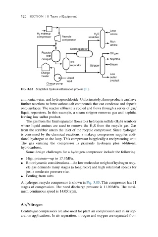
FIG. 3.82 Simplified hydrodesulferization process [31].
ammonia, water, and hydrogen chloride. Unfortunately, these products can have
further reactions to form various salt compounds that can condense and deposit
onto surfaces. The reactor effluent is cooled and flows through a series of gas/
liquid separators. In this example, a steam stripper removes gas and naphtha
leaving low sulfur product.
The gas from the final separator flows to a hydrogen sulfide (H 2 S) scrubber
where liquid amines are used to remove the H 2 S from the recycle gas. Gas
from the scrubber enters the inlet of the recycle compressor. Since hydrogen
is consumed by the chemical reactions, a makeup compressor supplies addi-
tional hydrogen to the loop. This compressor is typically a reciprocating unit.
The gas entering the compressor is primarily hydrogen plus additional
hydrocarbons.
Some design challenges for a hydrogen compressor include the following:
l High pressure—up to 17.3MPa.
l Rotordynamic considerations—the low molecular weight of hydrogen recy-
cle gas demands many stages (a long rotor) and high rotational speeds for
just a moderate pressure rise.
l Fouling from salts.
A hydrogen recycle compressor is shown in Fig. 3.83. This compressor has 11
stages of compression. The rated discharge pressure is 11.00MPa. The maxi-
mum continuous speed is 14,051rpm.
Air/Nitrogen
Centrifugal compressors are also used for plant air compression and in air sep-
aration applications. In air separation, nitrogen and oxygen are separated from