
Page 229 - Compression Machinery for Oil and Gas
P. 229
218 SECTION II Types of Equipment
FIG. 5.37 Component layout for suction valve closing regulation. (Courtesy of Ariel Corporation.)
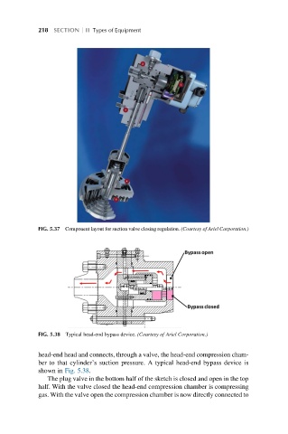
FIG. 5.38 Typical head-end bypass device. (Courtesy of Ariel Corporation.)
head-end head and connects, through a valve, the head-end compression cham-
ber to that cylinder’s suction pressure. A typical head-end bypass device is
shown in Fig. 5.38.
The plug valve in the bottom half of the sketch is closed and open in the top
half. With the valve closed the head-end compression chamber is compressing
gas. With the valve open the compression chamber is now directly connected to