
Page 232 - Compression Machinery for Oil and Gas
P. 232
Reciprocating Compressors Chapter 5 221
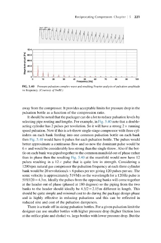
FIG. 5.40 Pressure pulsation complex wave and resulting Fourier analysis of pulsation amplitude
vs frequency. (Courtesy of SwRI.)
away from the compressor. It provides acceptable limits for pressure drop in the
pulsation bottle as a function of the compression ratio.
It should be noted that the packager can do a lot to reduce pulsation levels by
selecting pipe routing and lengths. For example, in Fig. 5.40 note that a double-
acting cylinder has 2 pulses per revolution. So it will have a strong 2 running
speed pulsation. Now if this is a 6-throw single-stage compressor with three cyl-
inders on each bank feeding into one common pulsation bottle on each bank
then Fig. 5.40 would have 6 pulses for each pulsation bottle. The pulses would
better approximate a continuous flow and so now the dominant pulse would be
6 and would be considerably less strong than the single throw. Also if the bot-
tle on each bank was piped together to the common manifold out of phase rather
than in phase then the resulting Fig. 5.40 at the manifold would now have 12
pulses resulting in a 12 pulse that is quite low in strength. Considering a
1200rpm natural gas compressor the pulsation frequency at each three cylinder
bank would be 20 revolutions/s 6 pulses per rev giving 120 pulses per sec. The
sonic velocity is approximately 519M/s so the wavelength for a 120Hz pulse is
519/120¼4.3m. Ideally the pulses from the opposing banks will come together
at the header out of phase (phased at 180 degrees) so the piping from the two
banks to the header should ideally be 4.3/2¼2.15m different in length. This
should be quite simple and minimal cost to do during the package design phase
and is highly effective in reducing pulsations and this can be reflected in
reduced size and cost of the pulsation dampeners.
There is a trade off in sizing pulsation bottles. For a given pulsation limit the
designer can use smaller bottles with higher pressure drop (higher friction loss
at the orifice plate and choke) vs. large bottles with lower pressure drop. But the