
Page 239 - Compression Machinery for Oil and Gas
P. 239
II Types of Equipment
228 SECTION
Motor
Coupling
Reciprocating
compressor
5 24 25 26 27 23 22 21 20 29 28 17 1819 15 16 1314 6 11 12 10 9 8 7 160 120 80 40 Axial location (in) SwRI.)
of
4
(Courtesy
3
2
1
0
20 10 0 –10 –20 graphics.
Shaft radius (in)
and
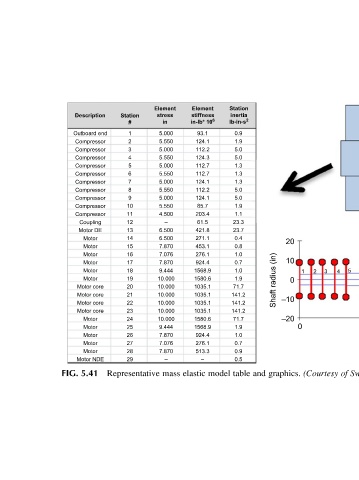
Station inertia lb-in-s 2 0.9 1.9 5.0 5.0 1.3 1.3 1.3 5.0 5.0 1.9 1.1 23.3 23.7 0.4 0.8 1.0 0.7 1.0 1.9 71.7 141.2 141.2 141.2 71.7 1.9 1.0 0.7 0.9 0.5 table
model
Element stiffness in-lb* 10 6 93.1 124.1 112.2 124.3 112.7 112.7 124.1 112.2 124.1 85.7 203.4 61.5 421.8 271.1 453.1 276.1 924.4 1568.9 1580.6 1035.1 1035.1 1035.1 1035.1 1580.6 1568.9 924.4 276.1 513.3 – elastic
Element stress in 5.000 5.550 5.000 5.550 5.000 5.550 5.000 5.550 5.000 5.550 4.500 – 6.500 6.500 7.870 7.076 7.870 9.444 10.000 10.000 10.000 10.000 10.000 10.000 9.444 7.870 7.076 7.870 – mass
Station # 1 2 3 4 5 6 7 8 9 10 11 12 13 14 15 16 17 18 19 20 21 22 23 24 25 26 27 28 29 Representative
Description Outboard end Compressor Compressor Compressor Compressor Compressor Compressor Compressor Compressor Compressor Compressor Coupling Motor DE Motor Motor Motor Motor Motor Motor Motor core Motor core Motor core Motor core Motor Motor Motor Motor Motor Motor NDE 5.41
FIG.