
Page 241 - Compression Machinery for Oil and Gas
P. 241
Reciprocating Compressors Chapter 5 229
L 2
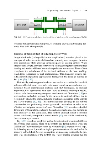
L 1
Drive shaft (1/3)L 1 (2/3)L 1 (2/3)L 2 (1/3)L 2 Driven shaft
FIG. 5.42 1/3 Penetration rule for torsional modeling of interference fit hubs. (Courtesy of SwRI.)
torsional damage tolerance standpoint, of avoiding keyways and utilizing gen-
erous fillet radii when possible.
Torsional Stiffening Effect of Induction Motor Webs
Longitudinal webs (colloquially known as spider bars) are often placed at the
mid-span of induction motor shafts and are primarily used to support the rotor
core laminations while allowing sufficient space for cooling airflow. When
subjected to a torque, the webs experience a loading configuration that includes
bending and torsion while the base shaft experiences pure torsion. These effects
complicate the calculation of the torsional stiffness of the base shafting,
which tends to increase for such configurations. This discussion seeks to pro-
vide a simplified practical approach for dealing with this issue, as outlined in
Ref. [10] (Fig. 5.45).
Historically, various approaches have been used to account for the base shaft
stiffening effect of motor core webs in torsional rotordynamics, including geo-
metrically based approximation methods and FEA techniques. In practical
experience, FEA approaches have been found to produce meaningful results,
but tend to be time consuming compared to other methods. Nestorides [11] pre-
sents various methods to account for the increase in torsional stiffness due to
webs rigidly attached to shafts, including a technique described as the Griffith
and Taylor method [12, 13]. This method requires dividing up the webbed
cross-section and performing various geometric calculations to arrive at an
effective second polar moment of area. Nestorides [11] provides a detailed
description of this method, including the sectioning techniques and the tabular
data necessary for the calculation. This method, although found to produce
results satisfactorily comparable to FEA results [10], can still be considerably
time consuming to execute.
Eq. (5.12) provides a simplified method for estimating the torsional stiffness
of a webbed shaft section, based on the Griffith and Taylor method. While the
Griffith and Taylor method presented by Nestorides [11] requires several steps,
the following approach provides a single equation to estimate the torsional stiff-
ness of a webbed shaft. Several assumptions are necessary to simplify the pro-
cess. This interpretation of the Griffith and Taylor method assumes that the