
Page 246 - Compression Machinery for Oil and Gas
P. 246
232 SECTION II Types of Equipment
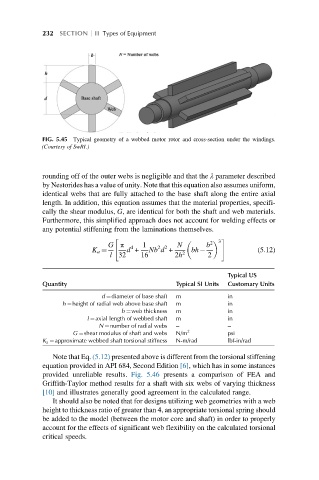
FIG. 5.45 Typical geometry of a webbed motor rotor and cross-section under the windings.
(Courtesy of SwRI.)
rounding off of the outer webs is negligible and that the λ parameter described
by Nestorides has a value of unity. Note that this equation also assumes uniform,
identical webs that are fully attached to the base shaft along the entire axial
length. In addition, this equation assumes that the material properties, specifi-
cally the shear modulus, G, are identical for both the shaft and web materials.
Furthermore, this simplified approach does not account for welding effects or
any potential stiffening from the laminations themselves.
" 3 #
G π 1 N b 2
2 2
4
K a ¼ d + Nb d + bh (5.12)
l 32 16 2h 2 2
Typical US
Quantity Typical SI Units Customary Units
d ¼diameter of base shaft m in
h ¼height of radial web above base shaft m in
b ¼web thickness m in
l ¼axial length of webbed shaft m in
N ¼number of radial webs – –
G ¼shear modulus of shaft and webs N/m 2 psi
K a ¼approximate webbed shaft torsional stiffness N-m/rad lbf-in/rad
Note that Eq. (5.12) presented above is different from the torsional stiffening
equation provided in API 684, Second Edition [6], which has in some instances
provided unreliable results. Fig. 5.46 presents a comparison of FEA and
Griffith-Taylor method results for a shaft with six webs of varying thickness
[10] and illustrates generally good agreement in the calculated range.
It should also be noted that for designs utilizing web geometries with a web
height to thickness ratio of greater than 4, an appropriate torsional spring should
be added to the model (between the motor core and shaft) in order to properly
account for the effects of significant web flexibility on the calculated torsional
critical speeds.