
Page 248 - Compression Machinery for Oil and Gas
P. 248
234 SECTION II Types of Equipment
1.00
0.75
Normalized amplitude –0.25 Compressor Coupling Motor
0.50
0.25
0.00
–0.50
–0.75
Mode 1: 5000 cpm (83.33 Hz)
–1.00
0 50 100 150 200 250
Length (in)
FIG. 5.47 Typical torsional mode shape. (Courtesy of SwRI.)
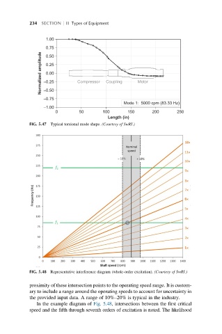
FIG. 5.48 Representative interference diagram (whole-order excitation). (Courtesy of SwRI.)
proximity of these intersection points to the operating speed range. It is custom-
ary to include a range around the operating speeds to account for uncertainty in
the provided input data. A range of 10%–20% is typical in the industry.
In the example diagram of Fig. 5.48, intersections between the first critical
speed and the fifth through seventh orders of excitation is noted. The likelihood