
Page 249 - Compression Machinery for Oil and Gas
P. 249
Reciprocating Compressors Chapter 5 235
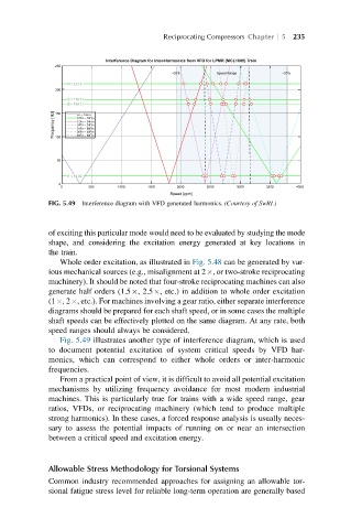
Interference Diagram for Inter-Harmonics from VFD for LPMR (MCL1605) Train
250
+20% Speed Range –20%
f4 = 212.3
200
f3 = 178.77
f2 = 169.11
Frequency [Hz] 100 Fn – 12Fm
150
12Fn – 12Fm
12Fn – 24Fm
24Fn – 24Fm
24Fn – 36Fm
36Fn – 48Fm
48Fn – 60Fm
50
f1 = 16.05
0
0 500 1000 1500 2000 2500 3000 3500 4000
Speed [rpm]
FIG. 5.49 Interference diagram with VFD generated harmonics. (Courtesy of SwRI.)
of exciting this particular mode would need to be evaluated by studying the mode
shape, and considering the excitation energy generated at key locations in
the train.
Whole order excitation, as illustrated in Fig. 5.48 can be generated by var-
ious mechanical sources (e.g., misalignment at 2 , or two-stroke reciprocating
machinery). It should be noted that four-stroke reciprocating machines can also
generate half orders (1.5 , 2.5 , etc.) in addition to whole order excitation
(1 ,2 , etc.). For machines involving a gear ratio, either separate interference
diagrams should be prepared for each shaft speed, or in some cases the multiple
shaft speeds can be effectively plotted on the same diagram. At any rate, both
speed ranges should always be considered.
Fig. 5.49 illustrates another type of interference diagram, which is used
to document potential excitation of system critical speeds by VFD har-
monics, which can correspond to either whole orders or inter-harmonic
frequencies.
From a practical point of view, it is difficult to avoid all potential excitation
mechanisms by utilizing frequency avoidance for most modern industrial
machines. This is particularly true for trains with a wide speed range, gear
ratios, VFDs, or reciprocating machinery (which tend to produce multiple
strong harmonics). In these cases, a forced response analysis is usually neces-
sary to assess the potential impacts of running on or near an intersection
between a critical speed and excitation energy.
Allowable Stress Methodology for Torsional Systems
Common industry recommended approaches for assigning an allowable tor-
sional fatigue stress level for reliable long-term operation are generally based