
Page 251 - Compression Machinery for Oil and Gas
P. 251
Reciprocating Compressors Chapter 5 237
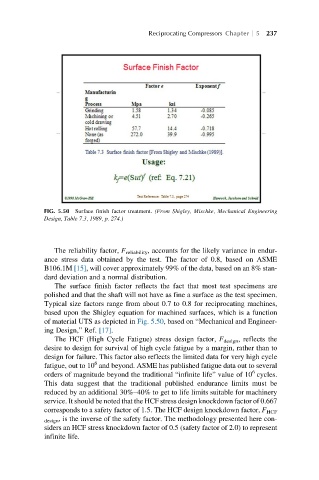
FIG. 5.50 Surface finish factor treatment. (From Shigley, Mischke, Mechanical Engineering
Design, Table 7.3, 1989, p. 274.)
The reliability factor, F reliability , accounts for the likely variance in endur-
ance stress data obtained by the test. The factor of 0.8, based on ASME
B106.1M [15], will cover approximately 99% of the data, based on an 8% stan-
dard deviation and a normal distribution.
The surface finish factor reflects the fact that most test specimens are
polished and that the shaft will not have as fine a surface as the test specimen.
Typical size factors range from about 0.7 to 0.8 for reciprocating machines,
based upon the Shigley equation for machined surfaces, which is a function
of material UTS as depicted in Fig. 5.50, based on “Mechanical and Engineer-
ing Design,” Ref. [17].
The HCF (High Cycle Fatigue) stress design factor, F design , reflects the
desire to design for survival of high cycle fatigue by a margin, rather than to
design for failure. This factor also reflects the limited data for very high cycle
6
fatigue, out to 10 and beyond. ASME has published fatigue data out to several
6
orders of magnitude beyond the traditional “infinite life” value of 10 cycles.
This data suggest that the traditional published endurance limits must be
reduced by an additional 30%–40% to get to life limits suitable for machinery
service. It should be noted that the HCF stress design knockdown factor of 0.667
corresponds to a safety factor of 1.5. The HCF design knockdown factor, F HCF
design , is the inverse of the safety factor. The methodology presented here con-
siders an HCF stress knockdown factor of 0.5 (safety factor of 2.0) to represent
infinite life.