Page 256 - Compression Machinery for Oil and Gas
P. 256

Reciprocating Compressors Chapter  5 241


                  4
                         Dynamic torque          Maximum allowable stress and computed combined stress
                × 10
              15                              12,000
                                                               Design factor = 1.5
                              Coupling
                                                  Design factor = 1.5
                                              10,000
                                                              Design factor = 2.0
              10                               8000
                                                  Design factor = 2.0
              in-lbs (pk)                    psi (pk)  6000
               5                               4000
                                               2000
                                                0
               0
               0     5    10   15   20   25      0    5    10   15   20    25
                           Field                             Field
                  Compressor    Motor              Compressor     Motor
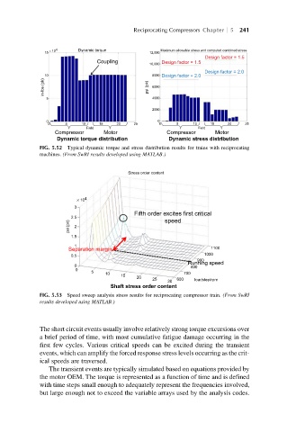
                  Dynamic torque distribution       Dynamic stress distribution
             FIG. 5.52 Typical dynamic torque and stress distribution results for trains with reciprocating
             machines. (From SwRI results developed using MATLAB.)
                                        Stress order content


                        × 10 4
                       3
                                         Fifth order excites first critical
                      2.5
                      psi (pk)  2                  speed

                      1.5
                       1
                                                                1100
                      Separation margin
                                                              1000
                      0.5
                                                            900
                                                         Running speed
                       0
                                                          800
                        0
                            5
                                 10                     700
                                     15
                                          20
                                               25     600
                                                           loadstep/rpm
                                                   30
                                  Shaft stress order content
             FIG. 5.53 Speed sweep analysis stress results for reciprocating compressor train. (From SwRI
             results developed using MATLAB.)
             The short circuit events usually involve relatively strong torque excursions over
             a brief period of time, with most cumulative fatigue damage occurring in the
             first few cycles. Various critical speeds can be excited during the transient
             events, which can amplify the forced response stress levels occurring as the crit-
             ical speeds are traversed.
                The transient events are typically simulated based on equations provided by
             the motor OEM. The torque is represented as a function of time and is defined
             with time steps small enough to adequately represent the frequencies involved,
             but large enough not to exceed the variable arrays used by the analysis codes.
   251   252   253   254   255   256   257   258   259   260   261