
Page 250 - Compression Machinery for Oil and Gas
P. 250
236 SECTION II Types of Equipment
on a standardized ultimate tensile strength (UTS) reduction methods. In the
absence of validated fatigue data for the shaft material in question, an effective
endurance limit is generated. On approach is based on Military Standard 167
[14], which involves dividing the UTS by 25 to arrive at an endurance limit.
This approach, although simple to apply, can be quite conservative. Another
common method starts with UTS and applies a series of reduction factors.
The suggested values for these factors represent a conservative interpretation
of the method described by ASME B106.1M [15].
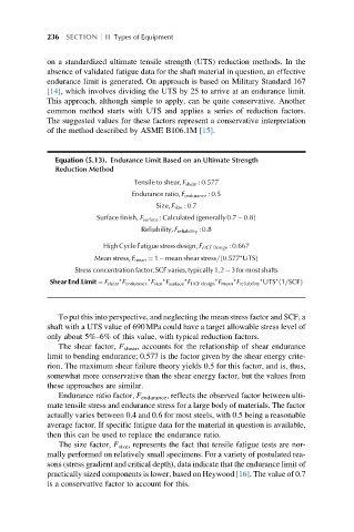
Equation (5.13). Endurance Limit Based on an Ultimate Strength
Reduction Method
Tensile to shear,F shear : 0:577
Endurance ratio,F endurance : 0:5
Size,F size : 0:7
Surface finish, F surface : Calculated generally 0:7 0:8ð Þ
Reliability,F reliability : 0:8
High Cycle Fatigue stressdesign,F HCF Design : 0:667
Mean stress,F mean ¼ 1 mean shear stress= 0:577 ∗ UTSð Þ
Stress concentration factor,SCFvaries,typically 1:2 3 for most shafts
∗ ∗ ∗ ∗ ∗ ∗ ∗
Shear End:Limit ¼ F shear F endurance F size F surface F HCF design F mean F reliability UTS ∗ 1=SCFð Þ
To put this into perspective, and neglecting the mean stress factor and SCF, a
shaft with a UTS value of 690MPa could have a target allowable stress level of
only about 5%–6% of this value, with typical reduction factors.
The shear factor, F shear , accounts for the relationship of shear endurance
limit to bending endurance; 0.577 is the factor given by the shear energy crite-
rion. The maximum shear failure theory yields 0.5 for this factor, and is, thus,
somewhat more conservative than the shear energy factor, but the values from
these approaches are similar.
Endurance ratio factor, F endurance , reflects the observed factor between ulti-
mate tensile stress and endurance stress for a large body of materials. The factor
actually varies between 0.4 and 0.6 for most steels, with 0.5 being a reasonable
average factor. If specific fatigue data for the material in question is available,
then this can be used to replace the endurance ratio.
The size factor, F size , represents the fact that tensile fatigue tests are nor-
mally performed on relatively small specimens. For a variety of postulated rea-
sons (stress gradient and critical depth), data indicate that the endurance limit of
practically sized components is lower, based on Heywood [16]. The value of 0.7
is a conservative factor to account for this.