
Page 364 - Compression Machinery for Oil and Gas
P. 364
348 SECTION II Types of Equipment
Steam in
Nozzle Moving
vones buckets
atio
fixed fixed
Fixed Moving
P Steam pressure
Steam
speed
V
A
B C
Velocity-compounded
(curtis) stage and
Pressure-compounded Reaction stage
reaction stages
(rateau) stage
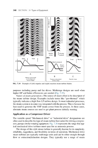
FIG. 7.34 Example of (left) impulse and (right) reaction steam turbine blades.
purposes including pump and fan drives. Multistage designs are used when
higher HP and better efficiencies are needed (Fig. 7.35).
Nature of steam generation—The source of steam often is the descriptor of
the steam turbine design. Examples include terms like “geo-thermal” which
typically indicates a high flow LP turbine design. In most industrial processes,
the steam system is in some way integrated with the process. This is because the
heat used to generate the VHP steam comes from the process. In these cases,
alternate steam sources are used to get plant process initially running.
Application as a Compressor Driver
The variable speed “Mechanical drive” or “industrial drive” designations are
often used to describe the type of steam turbine best suited for driving compres-
sors, pumps similar rotating equipment. Fig. 7.36 represents the range that typ-
ical mechanical drive turbines must span for an ammonia process.
The design of this style steam turbine is generally known for its simplicity,
reliability, ruggedness, and flexibility in terms of operation. Mechanical drive
steam turbines are typically multistage units and can be either straight through
flow or extraction/induction designs. They typically use a range of steam