
Page 367 - Compression Machinery for Oil and Gas
P. 367
350 SECTION II Types of Equipment
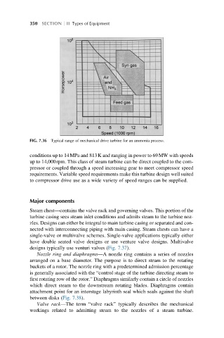
FIG. 7.36 Typical range of mechanical drive turbine for an ammonia process.
conditions up to 14MPa and 813K and ranging in power to 69MW with speeds
up to 14,000rpm. This class of steam turbine can be direct coupled to the com-
pressor or coupled through a speed increasing gear to meet compressor speed
requirements. Variable speed requirements make this turbine design well suited
to compressor drive use as a wide variety of speed ranges can be supplied.
Major components
Steam chest—contains the valve rack and governing valves. This portion of the
turbine casing sees steam inlet conditions and admits steam to the turbine noz-
zles. Designs can either be integral to main turbine casing or separated and con-
nected with interconnecting piping with main casing. Steam chests can have a
single-valve or multivalve schemes. Single-valve applications typically either
have double seated valve designs or use venture valve designs. Multivalve
designs typically use venturi valves (Fig. 7.37).
Nozzle ring and diaphragms—A nozzle ring contains a series of nozzles
arranged on a base diameter. The purpose is to direct steam to the rotating
buckets of a rotor. The nozzle ring with a predetermined admission percentage
is generally associated with the “control stage of the turbine directing steam to
first rotating row of the rotor.” Diaphragms similarly contain a circle of nozzles
which direct steam to the downstream rotating blades. Diaphragms contain
attachment point for an interstage labyrinth seal which seals against the shaft
between disks (Fig. 7.38).
Valve rack—The term “valve rack” typically describes the mechanical
workings related to admitting steam to the nozzles of a steam turbine.