
Page 372 - Compression Machinery for Oil and Gas
P. 372
Drivers Chapter 7 353
There are different categories of valve rack designs depending on the amount
of flow being passed, degree of control precision required.
Major types include:
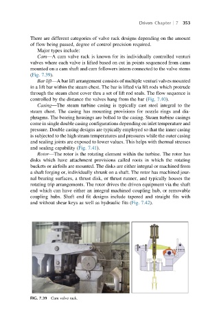
Cam—A cam valve rack is known for its individually controlled venturi
valves where each valve is lifted based on cut in points sequenced from cams
mounted on a cam shaft and cam followers intern connected to the valve stems
(Fig. 7.39).
Bar lift—A bar lift arrangement consists of multiple venturi valves mounted
in a lift bar within the steam chest. The bar is lifted via lift rods which protrude
through the steam chest cover thru a set of lift rod seals. The flow sequence is
controlled by the distance the valves hang from the bar (Fig. 7.40).
Casing—The steam turbine casing is typically cast steel integral to the
steam chest. The casing has mounting provisions for nozzle rings and dia-
phragms. The bearing housings are bolted to the casing. Steam turbine casings
come in single double casing configurations depending on inlet temperature and
pressure. Double casing designs are typically employed so that the inner casing
is subjected to the high steam temperatures and pressures while the outer casing
and sealing joints are exposed to lower values. This helps with thermal stresses
and sealing capability (Fig. 7.41).
Rotor—The rotor is the rotating element within the turbine. The rotor has
disks which have attachment provisions called roots in which the rotating
buckets or airfoils are mounted. The disks are either integral or machined from
a shaft forging or, individually shrunk on a shaft. The rotor has machined jour-
nal bearing surfaces, a thrust disk, or thrust runner, and typically houses the
rotating trip arrangements. The rotor drives the driven equipment via the shaft
end which can have either an integral machined coupling hub, or removable
coupling hubs. Shaft end fit designs include tapered and straight fits with
and without shear keys as well as hydraulic fits (Fig. 7.42).
FIG. 7.39 Cam valve rack.