
Page 363 - Compression Machinery for Oil and Gas
P. 363
Drivers Chapter 7 347
High pressure steam
Load: driven equipment
Turbine Load
Surface
To boiler
condenser
P
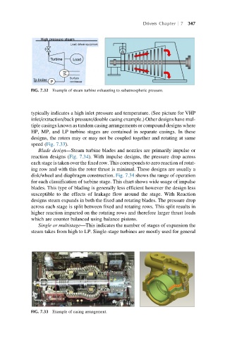
FIG. 7.32 Example of steam turbine exhausting to subatmospheric pressure.
typically indicates a high inlet pressure and temperature. (See picture for VHP
inlet/extraction/back pressure/double casing example.) Other designs have mul-
tiple casings known as tandem casing arrangements or compound designs where
HP, MP, and LP turbine stages are contained in separate casings. In these
designs, the rotors may or may not be coupled together and rotating at same
speed (Fig. 7.33).
Blade design—Steam turbine blades and nozzles are primarily impulse or
reaction designs (Fig. 7.34). With impulse designs, the pressure drop across
each stage is taken over the fixed row. This corresponds to zero reaction of rotat-
ing row and with this the rotor thrust is minimal. These designs are usually a
disk/wheel and diaphragm construction. Fig. 7.34 shows the range of operation
for each classification of turbine stage. This chart shows wide usage of impulse
blades. This type of blading is generally less efficient however the design less
susceptible to the effects of leakage flow around the stage. With Reaction
designs steam expands in both the fixed and rotating blades. The pressure drop
across each stage is split between fixed and rotating rows. This split results in
higher reaction imparted on the rotating rows and therefore larger thrust loads
which are counter balanced using balance pistons.
Single or multistage—This indicates the number of stages of expansion the
steam takes from high to LP. Single-stage turbines are mostly used for general
FIG. 7.33 Example of casing arrangement.