
Page 40 - Compression Machinery for Oil and Gas
P. 40
32 SECTION II Types of Equipment
higher ratios. In gas gathering, we may find pressure ratios of 25. The limits for
centrifugal compressors are typically either due to rotordynamic concerns,
which limit the speed and length of the rotor, or by temperature limits. Higher
pressure ratios may require multiple compressor bodies per train, and the
capability for intercooling. The operating range required also depends on the
application. Since for many applications, pressure ratio and flow are correlated
by the compression system, range has to be seen in that context. On the other
hand, many applications only see one distinct operating condition. Depending
on the range of operating conditions, different control methods (variable speed,
variable geometry, recycle) may be used. For applications that require the
compressor to cover a wide range of operating conditions, good compressor
efficiency over a wide range is usually more important than high peak
efficiency.
Elements of an Inline Centrifugal Compressor
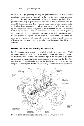
Fig. 3.1 shows a cross section of a barrel-style centrifugal compressor. While
the elements of a compressor will be discussed in detail later, they will be intro-
duced briefly here. Starting at the suction flange of the compressor, gas enters
the compressor through the inlet, whose purpose is to transition the flow from
radial to axial. In most barrel machines, fixed guide vanes help to reduce swirl
and provide an axisymmetric flow field coming into the compressor; however,
Casing
Inlet Stator
housing
assembly
Inlet
Discharge
guide vane volute
Impeller
Suction
flange
(Port)
Discharge
bearing and
seal assembly
Balance
piston
Discharge
flange
(Port)
Coupling hub or
balance sleeve Stator
Suction
bearing and Diffuser
seal assembly passage
FIG. 3.1 Barrel-style centrifugal compressor. (Courtesy of Solar Turbines, Inc.)