
Page 41 - Compression Machinery for Oil and Gas
P. 41
Centrifugal Compressors Chapter 3 33
some machines employ variable guide vanes to induce swirl and alter the rel-
ative flow angle seen by the compressor. After passing through the inlet, the
flow is directed into the impeller. It is the impellers responsibility to increase
the kinetic and potential energy of the gas by pushing it tangentially. This
requires torque that is transferred to the impeller by the shaft, which is ulti-
mately turned by a driver. After the flow leaves the impeller at high velocity,
it slows down in the diffuser building pressure. Due to losses and the heat of
compression, the gas builds up temperature as pressure increases. If there are
more compression stages, the gas leaves the diffuser and enters a return channel,
which directs the flow back to the inlet of the next stage. Once the gas leaves the
final stage of compression in a given section, it passes from the diffuser into a
collector or volute that directs the flow radially outward through the discharge
flange.
Other components consist of the casing that acts as an overall structure and
pressure vessel. Seals and walls separate the stages and ensure that gas follows
the primary path, minimizing leakage from the flow path. The shaft acts as the
inner boundary of the flow and also supports and drives the impellers, which in
turn performs the work and drives the gas. Bearings act as shaft support both
radially and axially and as part of an overall rotor-bearing dynamic system that
is tuned to allow robust operation of the machine.
Types/Configuration
Inline compressors typically have centrifugal stages located in between the
bearings; however, the casing can be packaged in a few different configurations.
They are typically a barrel style, horizontally split, or hermetically sealed.
Barrel
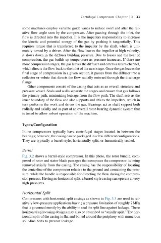
Fig. 3.2 shows a barrel-style compressor. In this photo, the rotor bundle, com-
posed of rotor and stator blade passages that composes the compressor, is being
removed axially from the casing. The casing has the responsibility of locating
the centerline of the compressor relative to the ground and containing the pres-
sure, while the bundle is responsible for directing the flow during the compres-
sion process. Having no horizontal split, a barrel-style casing can operate at very
high pressures.
Horizontal Split
Compressors with horizontal split casings as shown in Fig. 3.3 are used in rel-
atively low-pressure applications having a pressure limitation of roughly 7MPa
that is governed mostly by the ability to seal the split line against leakage. These
horizontal split casing designs may also be described as “axially split.” The hor-
izontal split of the casing is flat and bolted around the periphery with numerous
split-line bolts to prevent leakage.