
Page 46 - Compression Machinery for Oil and Gas
P. 46
Centrifugal Compressors Chapter 3 37
improve compressor efficiency. In the case of a dual flow arrangement, the sec-
tions run in parallel allowing for twice the flow through the compressor.
Compressor Components
Impeller
Impellers are at the heart of the compressor. Each impeller is part of a stage that
is selected to meet performance requirements. Impellers are selected based on
aerodynamic performance and mechanical integrity. Mechanical integrity is
typically evaluated by finite element analysis (FEA), while aerodynamic perfor-
mance is evaluated by a combination of one-dimensional (1D) and computa-
tional fluid dynamic (CFD) tools.
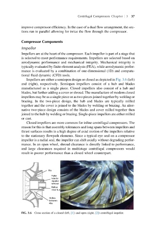
Impellers are either a semiopen design or closed as depicted in Fig. 3.6 (left)
and (right), respectively. Semiopen impellers consist of a hub and blades
manufactured as a single piece. Closed impellers also consist of a hub and
blades, but further adding a cover or shroud. The manufacture of modern closed
impellers may be as a single piece or as two pieces joined together by welding or
brazing. In the two-piece design, the hub and blades are typically milled
together and the cover is joined to the blades by welding or brazing. An alter-
native two-piece design consists of the blades and cover milled together then
joined to the hub by welding or brazing. Single-piece impellers are either milled
or cast.
Closed impellers are more common for inline centrifugal compressors. The
reason for this is that assembly tolerances and long spans between impellers and
thrust surfaces results in a high degree of axial motion of the impellers relative
to the stationary flowpath elements. Since a typical eye seal on a compressor
impeller is a radial seal, the impeller can shift axially without degrading perfor-
mance. In an open wheel, shroud clearance is directly linked to performance,
and large clearances required in multistage centrifugal compressors would
result in poorer performance than a closed wheel counterpart.
Rib
Puller
hole for
impeller
removal
Hollow
inner hub
Hollow
between
ribs
FIG. 3.6 Cross section of a closed (left, [1]) and open (right, [2]) centrifugal impeller.