
Page 51 - Compression Machinery for Oil and Gas
P. 51
42 SECTION II Types of Equipment
completely negates) the swirl. These devices are particularly effective for lab-
yrinth types, and may be used in either eye/interstage or balance piston seals.
Shunt holes, which are commonly utilized in either labyrinth or hole-pattern
balance piston seals, involve the use of redirected flow which is introduced
radially, thus opposing and reducing the swirl.
Shaft End
Shaft end seals are required to seal the gas inside the compressor at the point
where the compressor or piston shaft penetrates the casing. This vital sealing
function is necessary to prevent escape of process gas to the environment sur-
rounding the compressor. With the exception of reciprocating compressors, all
other types of compressors have rotating shafts. Accordingly, the applied type
of seals differs. Reciprocating compressors mainly use serial-arranged packing
rings for sealing the piston rod. For compressors with rotating shaft, however,
dry-gas-lubricated mechanical seals (dry gas seals (DGSs)) are commonly used.
The importance of oil-lubricated mechanical seals is reduced to applications
where requirements in pressure, speed, and power consumption are low.
Bushing-typesealsastheshaftendsealarereducedtoapplicationswhereleakage
requirements play a minor role. Labyrinths can be considered technically obso-
lete. However, bushing-type carbon ring seals or labyrinth seals are commonly
used as separation seal mounted between the DGS and the shaft bearing. Their
function is both to protect the DGS from spray oil and to prevent uncontrolled
process gas entry into the bearing cavity in the event of a total failure of the DGS.
The today’s most common type of shaft end seal in the oil and gas industry is
based on DGS technology. This triumphal procession goes back to the end of the
1980s of the last century. The use of DGSs in the place of oil lubricated mechan-
ical seals improves mechanical efficiency as the shear and friction power of the
seal is significant reduced. The application limit of a single oil-lubricated seal
stage is about 100m/s peripheral speed at the outer diameter of the seal faces
and 50bar differential pressure. By comparison, gas seals achieve more than
200m/s and a pressure difference of more than 450bar per single seal stage.
The resulting degrees of freedom in the compressor design justify the success
of gas sealing technology.
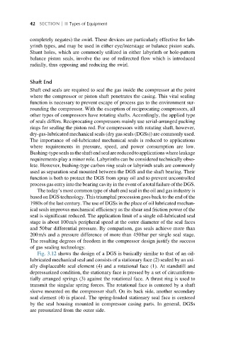
Fig. 3.12 shows the design of a DGS is basically similar to that of an oil-
lubricated mechanical seal and consists of a stationary face (2) sealed by an axi-
ally displaceable seal element (4) and a rotational face (1). At standstill and
depressurized condition, the stationary face is pressed by a set of circumferen-
tially arranged springs (3) against the rotational face. A thrust ring is used to
transmit the singular spring forces. The rotational face is centered by a shaft
sleeve mounted on the compressor shaft. On its back side, another secondary
seal element (4) is placed. The spring-loaded stationary seal face is centered
by the seal housing mounted in compressor casing parts. In general, DGSs
are pressurized from the outer side.