
Page 47 - Compression Machinery for Oil and Gas
P. 47
38 SECTION II Types of Equipment
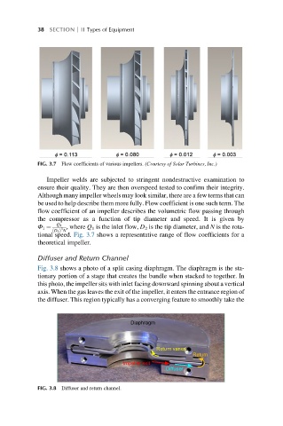
FIG. 3.7 Flow coefficients of various impellers. (Courtesy of Solar Turbines, Inc.)
Impeller welds are subjected to stringent nondestructive examination to
ensure their quality. They are then overspeed tested to confirm their integrity.
Although many impeller wheels may look similar, there are a few terms that can
be used to help describe them more fully. Flow coefficient is one such term. The
flow coefficient of an impeller describes the volumetric flow passing through
the compressor as a function of tip diameter and speed. It is given by
Q 1
Φ 1 ¼ 3 , where Q 1 is the inlet flow, D 2 is the tip diameter, and N is the rota-
ð D 2 Þ N
tional speed. Fig. 3.7 shows a representative range of flow coefficients for a
theoretical impeller.
Diffuser and Return Channel
Fig. 3.8 shows a photo of a split casing diaphragm. The diaphragm is the sta-
tionary portion of a stage that creates the bundle when stacked to together. In
this photo, the impeller sits with inlet facing downward spinning about a vertical
axis. When the gas leaves the exit of the impeller, it enters the entrance region of
the diffuser. This region typically has a converging feature to smoothly take the
Diaphragm
Return vanes
Return
Impeller exit
Diffuser
FIG. 3.8 Diffuser and return channel.