
Page 50 - Compression Machinery for Oil and Gas
P. 50
Centrifugal Compressors Chapter 3 41
These seals are normally of the labyrinth or hole-pattern variety. Labyrinth
types generally allow low leakage rates (which is beneficial from a compressor
performance standpoint) since tighter clearances may be used because the seals
are usually made of soft materials (e.g., aluminum). These materials are
unlikely to damage the shafting during intermittent contact. However, these
seals do little to counteract the destabilizing cross-coupling forces that are gen-
erated in the impellers and seals. This can increase the potential for self-excited
rotordynamic instabilities. Hole-pattern seals (which include the popular hon-
eycomb variety) require additional clearance, as they are generally made of
harder materials (e.g., Hastelloy) which can easily damage shafting. As a result,
these seals impose a slight penalty to compressor performance due to higher
leakage levels when compared to labyrinth types, but have the potential to
add significant stiffness and damping to the system, which can be very benefi-
cial from a rotordynamic stability standpoint.
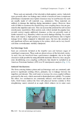
Eye/Interstage Seals
Seals are commonly included at the impeller eyes and between stages of
centrifugal compressors. These seals are almost always of the labyrinth variety.
As such, they are beneficial from a performance standpoint, due to the tight
clearances made possible by using abradable materials. However, they can gen-
erate destabilizing cross-coupling coefficients that should be included in an
American Petroleum Institute (API) level II rotordynamic analysis (Fig. 3.11).
Antiswirl Mechanisms
The flows entering balance piston and eye/interstage seals are commonly sub-
jected to significant swirling effects, primarily due to leakage between the
impellers and shrouds. This swirl tends to increase the cross-coupled stiffness
generated by the seals, which can result in diminished rotor stability. To counter
this effect, two mechanisms are commonly utilized: swirl brakes and shunt
holes. Swirl brakes redirect the flow with physical barriers (similar to flow
straightening vanes) oriented at an angle which reduces (or in some cases
Eye seal
Interstage seal
FIG. 3.11 Eye seal and interstage seal location.