
Page 54 - Compression Machinery for Oil and Gas
P. 54
Centrifugal Compressors Chapter 3 45
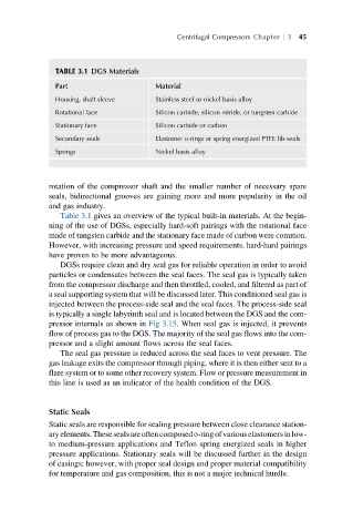
TABLE 3.1 DGS Materials
Part Material
Housing, shaft sleeve Stainless steel or nickel basis alloy
Rotational face Silicon carbide, silicon nitride, or tungsten carbide
Stationary face Silicon carbide or carbon
Secondary seals Elastomer o-rings or spring energized PTFE lib-seals
Springs Nickel basis alloy
rotation of the compressor shaft and the smaller number of necessary spare
seals, bidirectional grooves are gaining more and more popularity in the oil
and gas industry.
Table 3.1 gives an overview of the typical built-in materials. At the begin-
ning of the use of DGSs, especially hard-soft pairings with the rotational face
made of tungsten carbide and the stationary face made of carbon were common.
However, with increasing pressure and speed requirements, hard-hard pairings
have proven to be more advantageous.
DGSs require clean and dry seal gas for reliable operation in order to avoid
particles or condensates between the seal faces. The seal gas is typically taken
from the compressor discharge and then throttled, cooled, and filtered as part of
a seal supporting system that will be discussed later. This conditioned seal gas is
injected between the process-side seal and the seal faces. The process-side seal
is typically a single labyrinth seal and is located between the DGS and the com-
pressor internals as shown in Fig 3.15. When seal gas is injected, it prevents
flow of process gas to the DGS. The majority of the seal gas flows into the com-
pressor and a slight amount flows across the seal faces.
The seal gas pressure is reduced across the seal faces to vent pressure. The
gas leakage exits the compressor through piping, where it is then either sent to a
flare system or to some other recovery system. Flow or pressure measurement in
this line is used as an indicator of the health condition of the DGS.
Static Seals
Static seals are responsible for sealing pressure between close clearance station-
aryelements.Thesesealsareoftencomposedo-ringofvariouselastomersinlow-
to medium-pressure applications and Teflon spring energized seals in higher
pressure applications. Stationary seals will be discussed further in the design
of casings; however, with proper seal design and proper material compatibility
for temperature and gas composition, this is not a major technical hurdle.