
Page 451 - Compression Machinery for Oil and Gas
P. 451
Compressor System Design and Analysis Chapter 11 431
1E+3
Magnitude pk-pk [Pa] 6E+3
8E+3
4E+3
2E+3
0
0 10 20 30 40 50 60 70 80 90 100
Frequency [Hz]
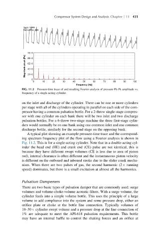
FIG. 11.2 Pressure-time trace of and resulting Fourier analysis of pressure Pk-Pk amplitude vs.
frequency of a single-acting cylinder.
on the inlet and discharge of the cylinder. There can be one or more cylinders
per stage with all of the cylinders operating in parallel on each side of the com-
pressor having a common pulsation bottle. For a 2-throw single-stage compres-
sor with one cylinder on each bank there will be two inlet and two discharge
pulsation bottles. For a 6-throw two-stage machine the three first-stage cylin-
ders would normally be on one bank using one common inlet and one common
discharge bottle, similarly for the second stage on the opposing bank.
A typical plot showing an example pressure-time trace and the correspond-
ing spectrum frequency plot of the flow using a Fourier analysis is shown in
Fig. 11.2. This is for a single-acting cylinder. Note that in a double-acting cyl-
inder the head end (HE) and crank end (CE) pulse are not identical, this is
because they have different swept volumes (CE is less due to area of piston
rod), internal clearance is often different and the instantaneous piston velocity
is different on the outboard and inbound stroke due to the slider crank mecha-
nism. When there are two pulses of gas, the second harmonic (2 running
speed) dominates, but there is a small excitation at almost all the harmonics.
Pulsation Dampeners
There are two basic types of pulsation damper that are commonly used: surge
volumes and volume-choke-volume acoustic filters. With a surge volume, the
cylinder feeds into a simple volume bottle. This uses the principle of a large
volume to add compliance into the system and some pressure drop, either an
orifice plate or choke at the bottle line connection. Typically volumes of
10–30 cylinder swept volume and a pressure drop at the line connection of
1% are adequate to meet the API-618 pulsation requirements. This bottle
may have an internal baffle to control the shaking forces and an orifice at