
Page 448 - Compression Machinery for Oil and Gas
P. 448
428 SECTION III Applications
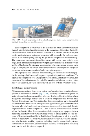
FIG. 11.1A Typical reciprocating skid layout and compressor station layout (compressors in
building). (Image Courtesy of Arielcorp.com.)
Each compressor is connected to the inlet and the outlet distribution header
through lateral piping lines that connect to the compressor skid piping. Typically
the skid includes an inlet scrubber or filter bottle to remove contaminants; the
cooler for the discharge piping can be on-skid with one cooler for each compres-
sor, or in the header piping cooling the gas for all compressors simultaneously.
The compressor can operate in multiple stages with one or more cylinders per
stage. Each intermediate stage has its own pipingsystem that can include a cooler
and/or a filter bottle. To attenuate pulsations from the compression process, each
stage of compression has a filter bottle either mounted on the cylinder flanges or
connected to the compressor inlet/outlet by a pipe segment.
The piping includes a recycle line connecting the suction and discharge pip-
ing for start-up, shutdown, and temporary operation in part-load conditions. To
operate the compressor over a range of flow conditions, speed can be varied, the
capacity of the cylinders can be varied by opening and closing pockets in the
end of the cylinder, or valve unloaders can be used to hold open the valves.
Centrifugal Compressors
All systems are unique; however, a typical configuration for a centrifugal com-
pressor is described as follows (Fig. 11.1B). Usually a compressor system or
station (centrifugal compressor) has inlet and discharge block isolation valves
along with a discharge check valve to isolate a compressor and prevent back
flow of downstream gas. The suction line has a pressurizing valve in parallel
with the suction block valve. This pressurizing valve is typically smaller than
the main inlet block valve and sometimes contains an orifice to control the rate
of pressurization of the compressor. There is also a blowdown valve located
within the loop to allow depressurization of the compression equipment when
necessary. This blowdown valve is usually routed to a flare system for safe dis-
posal of hydrocarbon fluid. If the fluid is inert like nitrogen or air it is usually
routed to atmosphere via a valve silencer connected to the valve outlet. The sys-
tem also includes auxiliary systems including electric power, fuel systems,
instrument air, lubrication, gas seal support systems, cooling system including
water or air, and filtration as required.