
Page 449 - Compression Machinery for Oil and Gas
P. 449
Compressor System Design and Analysis Chapter 11 429
Anti-surge
recycle valve
Suction scrubber
Suction Centrifugal
Discharge
Discharge Discharge
block valve compressor
cooler
check valve block valve
Pressurizing
valve
Drain to safe system
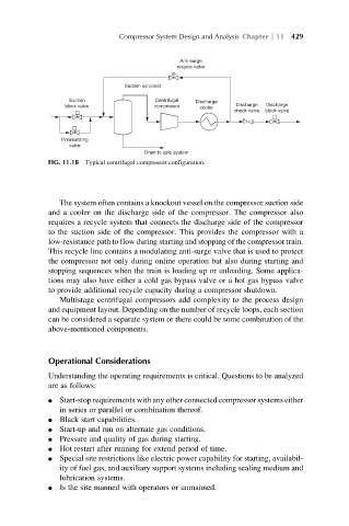
FIG. 11.1B Typical centrifugal compressor configuration.
The system often contains a knockout vessel on the compressor suction side
and a cooler on the discharge side of the compressor. The compressor also
requires a recycle system that connects the discharge side of the compressor
to the suction side of the compressor. This provides the compressor with a
low-resistance path to flow during starting and stopping of the compressor train.
This recycle line contains a modulating anti-surge valve that is used to protect
the compressor not only during online operation but also during starting and
stopping sequences when the train is loading up or unloading. Some applica-
tions may also have either a cold gas bypass valve or a hot gas bypass valve
to provide additional recycle capacity during a compressor shutdown.
Multistage centrifugal compressors add complexity to the process design
and equipment layout. Depending on the number of recycle loops, each section
can be considered a separate system or there could be some combination of the
above-mentioned components.
Operational Considerations
Understanding the operating requirements is critical. Questions to be analyzed
are as follows:
l Start-stop requirements with any other connected compressor systems either
in series or parallel or combination thereof.
l Black start capabilities.
l Start-up and run on alternate gas conditions.
l Pressure and quality of gas during starting.
l Hot restart after running for extend period of time.
l Special site restrictions like electric power capability for starting, availabil-
ity of fuel gas, and auxiliary support systems including sealing medium and
lubrication systems.
l Is the site manned with operators or unmanned.