
Page 90 - Compression Machinery for Oil and Gas
P. 90
Centrifugal Compressors Chapter 3 79
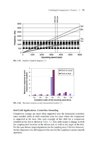
FIG. 3.43 Impeller Campbell diagram [17].
7 6 Point on cover
Maximum response at each measurement location 5 4 3 2
Point on hub
13´ 14´ 15´ 16´ 17´ 18´ 19´
0 1
Excitation order of the traveling wave force
FIG. 3.44 Maximum response at each measurement location [17].
Hot/Cold Applications, Centerline Mounting
Compressor casings are most often supported near the horizontal centerline
since sizeable shifts in shaft centerline exist for cases where the compressor
is supported at the base. One such example of this shift for a compressor
mounted at the feet is shown in Table 3.2. This shift creates a change in both
the coupling hub location on the driven end, as well as the angle of the hub.
For the case shown, target alignments for the coupling were 2.64mm; however,
the hot alignment was still targeted to be zero for the coupling to ensure smooth
operation.