
Page 91 - Compression Machinery for Oil and Gas
P. 91
80 SECTION II Types of Equipment
TABLE 3.2 Horizontal (X) and Vertical (Y) Shift in Foot Mounted Compressor
Centerline at a Discharge Temperature of 436K
Compressor Growth Compressor 436K
mm 0
X Inlet
mm 0.12
Y Inlet
mm 0
X Discharge
mm 1.05
Y Discharge
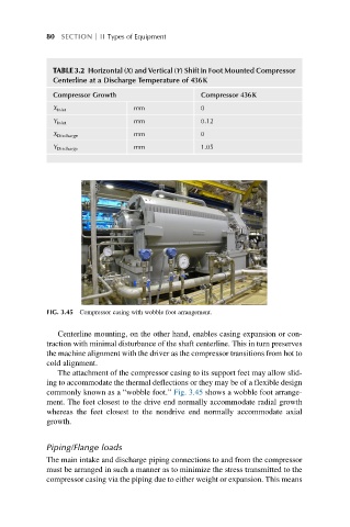
FIG. 3.45 Compressor casing with wobble foot arrangement.
Centerline mounting, on the other hand, enables casing expansion or con-
traction with minimal disturbance of the shaft centerline. This in turn preserves
the machine alignment with the driver as the compressor transitions from hot to
cold alignment.
The attachment of the compressor casing to its support feet may allow slid-
ing to accommodate the thermal deflections or they may be of a flexible design
commonly known as a “wobble foot.” Fig. 3.45 shows a wobble foot arrange-
ment. The feet closest to the drive end normally accommodate radial growth
whereas the feet closest to the nondrive end normally accommodate axial
growth.
Piping/Flange loads
The main intake and discharge piping connections to and from the compressor
must be arranged in such a manner as to minimize the stress transmitted to the
compressor casing via the piping due to either weight or expansion. This means