
Page 96 - Compression Machinery for Oil and Gas
P. 96
Centrifugal Compressors Chapter 3 85
0.8
Front cavity—Correlation
Front cavity—CFD analysis
Front cavity—Pressure measurement
Rear cavity—Correlation
0.7
Rear cavity—CFD analysis
0.6
Cavity swirl coefficient (q) 0.5
0.4
0.3
1 2 2 2
p(r)= p tip – — r(qw) (r tip – r )
2
0.2
0.02 0.03 0.04 0.05 0.06 0.07 0.08 0.09
Inlet flow coefficient (F)
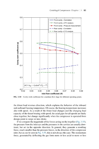
FIG. 3.50 Cavity swirl coefficient for a medium flow stage for different operating points.
the thrust load reverses direction, which explains the behavior of the inboard
and outboard bearing temperature. Of course, the bearing temperature increases
also with speed. As a result of the thrust load changes and the changing load
capacity of the thrust bearing with speed, the axial gaps for all speeds are fairly
close together, but change significantly when the compressor is operated from
design point to surge or into choke.
If we compare the magnitude of the forces acting on the impeller (Fig. 3.55),
the pressure from the inlet eye and the pressures in the cavities are usually dom-
inant, but act in the opposite direction. In general, they generate a resulting
force, much smaller than the pressure forces, in the direction of the compressor
inlet, but as can be seen in Fig. 3.55, this is not always the case. The momentum
force, generated by deflecting the gas form more or less axial to more or less