
Page 99 - Compression Machinery for Oil and Gas
P. 99
88 SECTION II Types of Equipment
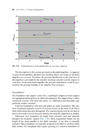
30 F pressure, inlet 2
1.5
20
1
10
F 0.5
momentum
F/F thrust 0 0
–0.5
–10
F –1
impeller
–20
–1.5
F
pressure, cavities
–2
–30
1 2 3 4 5 6
Stage
FIG. 3.55 Contributing forces to the impeller thrust in a six-stage compressor.
The descriptions in this section are based on shrouded impellers. As opposed
to open-faced impellers, that have free-standing blades, the blades in shrouded
impellers are covered. Therefore, the pressure distribution on the front face of
the impeller is governed by the impeller discharge pressure and the impact of
swirl flow. In an open-faced impeller, the pressure distribution would be gov-
erned by the pressure buildup in the impeller flow passages.
Foundation
The foundation and support system for a centrifugal compressor must support
the equipment and keep them in sufficient alignment. The support base is either
reinforced concrete with steel sole plates or a fabricated steel baseplate sup-
ported by another structure.
Concrete foundations with steel sole plates are quite economical. The con-
crete foundation typically consists of concrete beams on the order of 46–80cm
thick with reinforcing steel throughout. The concrete beams may be elevated as
part of an overall concrete structure thereby elevating the equipment as needed.
Fabricated steel baseplates are made from structural steel and typically
designed for perimeter support (Fig. 3.56). Main longitudinal beams run the
length of the string parallel to the shaft centerline. A top deck is normally
included. These baseplates are typically designed to be lifted or set down while
fully loaded. The baseplates may require grouting to a concrete foundation or