
Page 92 - Compression Machinery for Oil and Gas
P. 92
Centrifugal Compressors Chapter 3 81
the pipe flanges adjacent to the unit have to be aligned and parallel, and that the
piping must be supported with provisions for thermal expansion without exert-
ing a total strain on the compressor casing of more than just a very small per-
centage of the weight of the machine. Precautions should be taken if expansion
joints are used, since these do not necessarily reduce piping strains to a reason-
able magnitude unless the pressure forces exerted by the expansion joint are
compensated for and the spring forces are considered. If the piping is not ana-
lyzed carefully and stresses relieved to reasonable values, trouble can be
expected with casing distortion, bearing, shaft misalignment, vibration, and
generally rough operation.
Thrust Loads
An axial thrust load is generated on the compressor rotor by gas forces within
the machine. The overall thrust force can be determined from the sum of forces
acting at each impeller, at each shaft end, and at each seal. The overall axial
thrust load will vary over the compressor operating envelope.
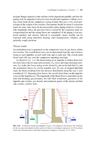
As shown in Fig. 3.46, the thrust acting on an impeller is broken down into
the static forces due to stage inlet pressure, F S1 (eye), and stage discharge pres-
sure, F S2 (hub), the forces acting on the shroud F D and on the hub disk F N and
the momentum forces F M (in the impeller eye). In case of stepped labyrinth
seals, the thrust resulting from the pressure distribution along the seal is also
considered [19]. Summing these forces, the overall thrust force on the impeller
is toward the impeller eye. The magnitude of the thrust force is dependent on the
inlet and discharge gas pressures, the inlet fluid momentum, geometry of the
impeller and cavities, gas density and rotational speed, of the shroud and hub
side cavities, and the seals.
F
o
F
N
F
F F
s1
M
s2
FIG. 3.46 Axial forces acting on an impeller. (Figure 7 of Y. Bidaut, D. Dessibourg, The challenge
for the accurate determination of the axial rotor thrust in centrifugal compressors, in: Proceedings
of the Asia Turbomachinery and Pump Symposium, Singapore, February 22–25, 2016.)