
Page 245 - Computational Fluid Dynamics for Engineers
P. 245
234 7. Boundary-Layer Equations
f* \ I X
(a) (b)
6
7
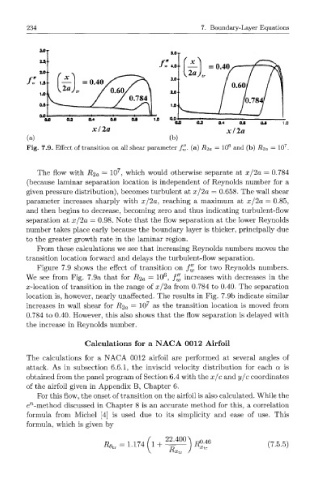
Fig. 7.9. Effect of transition on all shear parameter f£. (a) i?2a = 10 and (b) i?2a = 10 .
7
The flow with i?2a = 10 , which would otherwise separate at x/2a = 0.784
(because laminar separation location is independent of Reynolds number for a
given pressure distribution), becomes turbulent at x/2a — 0.658. The wall shear
parameter increases sharply with x/2a, reaching a maximum at x/2a = 0.85,
and then begins to decrease, becoming zero and thus indicating turbulent-flow
separation at x/2a = 0.98. Note that the flow separation at the lower Reynolds
number takes place early because the boundary layer is thicker, principally due
to the greater growth rate in the laminar region.
Prom these calculations we see that increasing Reynolds numbers moves the
transition location forward and delays the turbulent-flow separation.
Figure 7.9 shows the effect of transition on f^ for two Reynolds numbers.
6
We see from Fig. 7.9a that for i?2a = 10 , ^ increases with decreases in the
/
x-location of transition in the range of x/2a from 0.784 to 0.40. The separation
location is, however, nearly unaffected. The results in Fig. 7.9b indicate similar
increases in wall shear for i?2a = 10 7 as the transition location is moved from
0.784 to 0.40. However, this also shows that the flow separation is delayed with
the increase in Reynolds number.
Calculations for a N A C A 0012 Airfoil
The calculations for a NACA 0012 airfoil are performed at several angles of
attack. As in subsection 6.6.1, the inviscid velocity distribution for each a is
obtained from the panel program of Section 6.4 with the x/c and y/c coordinates
of the airfoil given in Appendix B, Chapter 6.
For this flow, the onset of transition on the airfoil is also calculated. While the
n
e -method discussed in Chapter 8 is an accurate method for this, a correlation
formula from Michel [4] is used due to its simplicity and ease of use. This
formula, which is given by
22.400 ,0.46
= 1.174 1 + (7.5.5)
R 6tr n
'XtT
~R Xtr