
Page 247 - Computational Fluid Dynamics for Engineers
P. 247
236 7. Boundary-Layer Equations
0.40
= 3 million
R c
0.30 R c = 9 million
si f\
0.20 L •
0.10 L
y
0.00 0.20
0.0 5.0 10.0 15.0 0.0 5.0 10.0 15.0
a a
00 (b)
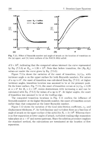
Fig. 7.11. Effect of Reynolds number and angle of attack on the location of transition on
the (a) upper, and (b) lower surfaces of the NACA 0012 airfoil.
6
of 3 x 10 , indicating that the computed values intersect the curve represented
6
by Eq. (7.5.5) at R Xtr = 1.20 x 10 . Note that before transition, the (R 0,R X)
values are under the curve given by Eq. (7.5.5).
Figure 7.11a shows the variation of the onset of transition, (s/c)t r , with
incidence angle a on the upper surface for both Reynolds numbers. For values
of a up to 6°, the onset of transition was calculated from Eq. (7.5.5): at higher
incidence angles, transition location was assumed to be at the pressure peak.
On the lower surface, Fig. 7.11b, the onset of transition occurs at (s/c)t r = 0.28
6
at a = 0° for R c = 3 x 10 , moves downstream with increasing a and can be
calculated with Eq. (7.5.5) for values of a up to 9°. At higher angles, the onset
of transition was assumed to be at the trailing edge.
The computed transition locations in Fig. 7.11 confirm the influence of
Reynolds number: at the higher Reynolds number, the onset of transition occurs
earlier than that computed at the lower Reynolds number.
Figure 7.12 shows the variation of the local skin-friction coefficient, cy, and
displacement thickness, <5*, for both laminar and turbulent flows as a function of
6
angle of attack on the upper surface of the airfoil for R c = 3 x 10 . Whereas there
is no flow separation at lower angles of attack, turbulent trailing-edge separation
takes place at a = 6° and moves upstream. Since the solution procedure employs
the standard method, the calculations are terminated at the location of flow
separation.