
Page 238 - Computational Modeling in Biomedical Engineering and Medical Physics
P. 238
Magnetic stimulation and therapy 227
x2x 0 Þ 1 y2y 0 Þ 1 z2z 0 Þ and ρ 5
2
2
with R 5 p ffiffiffiffiffiffiffiffiffiffiffiffiffiffiffiffiffiffiffiffiffiffiffiffiffiffiffiffiffiffiffiffiffiffiffiffiffiffiffiffiffiffiffiffiffiffiffiffiffiffiffiffiffiffiffiffiffiffiffi 2 p ffiffiffiffiffiffiffiffiffiffiffiffiffiffiffiffiffiffiffiffiffiffiffiffiffiffiffiffiffiffiffiffiffiffiffiffiffiffi 2
2
x2x 0 Þ 1 y2y 0 Þ as defined earlier. The
ð
ð
ð
ð
ð
total contribution of the coil ampere-turns to AF results in any point
P(x,y,z) by the integration of Eq. (7.10), only after the variable represented by the ϕ
angle, on a complete circumference, from 0 to 2π, and following all the turns of the
coil magnetic field applicator.
The spatial distribution of AF depends on the geometry of the magnetic field
applicator. Computational models like the one presented here are helpful during the
design process of the applicator and the electric circuit, by the control of shape, size,
the position of the coils and the equivalent circuit elements (inductance and resis-
tance). An optimization process could be easily conducted on criteria as follows:
(1) maximization of stimulation efficiency through the control of some parameters: AF
peak directed to the target zone for stimulation and precisely focused, while minimiz-
ing side effects (other peaks with lower amplitude or with opposite polarity); (2) han-
dling the applicator easily and without risk, by highlighting functional correlations
between design aspects and physical characteristics of the AF distribution inside the
body; and (3) the design of the electric circuit that includes the applicator for optimal
morphology of the AF waveform, lowest energy consumption, lowest heating, and
adequate time constants of the therapeutical process.
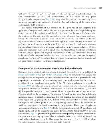
Example of activation function distribution inside the body
Illustrative results obtained with the assessment method presented here were published by
Esselle and Stuchly (1992) and Stuchly and Esselle (1992) for applicators with circular and
rectangular coils, either parallel with the air-body demarcation surface or perpendicular to it,
purposing the maximization of the stimulating main peak, while minimizing the occurrence
or effect of other nontherapeutical peaks of the AF spatial distribution. In a study by
Morega (2000) an analysis of some applicators with circular coils was performed, aiming to
compare the efficiency of operational performances. Two indices are defined: (1) focalization
(F) that quantifies the spatial concentration of AF and is equivalent to the target tissue area;
F is determined by the projection of the negative AF peak on the plane that includes the
embedded nerve—it should be minimized for best targeting the action on the intended
nerve region and (2) efficiency ratio (ER) defined by the absolute value of the ratio between
the negative and positive peaks of AF in neighboring areas—it should be maximized to
avoid hyperpolarization or chaotic stimulation in the proximity. Three types of applicators
were compared (as shown in Fig. 7.4): (1) the concentrated single-coil, (2) the double coil
(figure eight), and (3) the quadruple coil (like a flower). Besides the geometry of the coils
(left column), Fig. 7.4 presents their performances: corresponding AF spatial distribution in
the plane where the long cylindrical fiber is embedded (xOy, z 5 0.01 m) (central col-
umn) and the distribution along the fiber (x-axis direction, at y 5 0, z 5 0.01 m) where
the highest negative peak occurs on the nerve (right column).