
Page 253 -
P. 253
220 CHAPTER 7 / INPUT/OUTPUT
We can broadly classify external devices into three categories:
• Human readable: Suitable for communicating with the computer user
• Machine readable: Suitable for communicating with equipment
• Communication: Suitable for communicating with remote devices
Examples of human-readable devices are video display terminals (VDTs) and
printers. Examples of machine-readable devices are magnetic disk and tape systems,
and sensors and actuators, such as are used in a robotics application. Note that we
are viewing disk and tape systems as I/O devices in this chapter, whereas in Chapter 6
we viewed them as memory devices. From a functional point of view, these devices
are part of the memory hierarchy, and their use is appropriately discussed in
Chapter 6. From a structural point of view, these devices are controlled by I/O mod-
ules and are hence to be considered in this chapter.
Communication devices allow a computer to exchange data with a remote de-
vice, which may be a human-readable device, such as a terminal, a machine-readable
device, or even another computer.
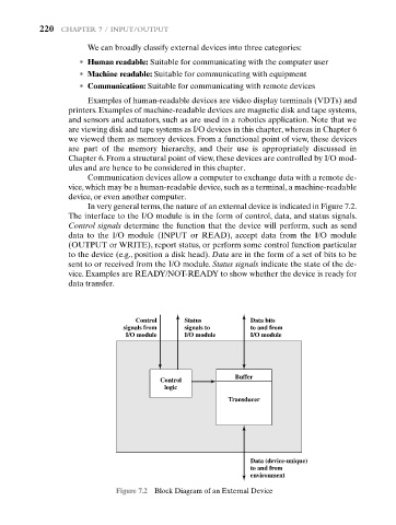
In very general terms, the nature of an external device is indicated in Figure 7.2.
The interface to the I/O module is in the form of control, data, and status signals.
Control signals determine the function that the device will perform, such as send
data to the I/O module (INPUT or READ), accept data from the I/O module
(OUTPUT or WRITE), report status, or perform some control function particular
to the device (e.g., position a disk head). Data are in the form of a set of bits to be
sent to or received from the I/O module. Status signals indicate the state of the de-
vice. Examples are READY/NOT-READY to show whether the device is ready for
data transfer.
Control Status Data bits
signals from signals to to and from
I/O module I/O module I/O module
Buffer
Control
logic
Transducer
Data (device-unique)
to and from
environment
Figure 7.2 Block Diagram of an External Device