
Page 257 -
P. 257
224 CHAPTER 7 / INPUT/OUTPUT
Interface to Interface to
system bus external device
Data
Data registers External
device
Data Status
lines interface
logic
Status/control registers Control
•
•
•
Address
Data
lines
External
I/O device Status
logic interface
Control logic
lines Control
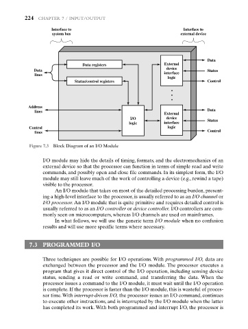
Figure 7.3 Block Diagram of an I/O Module
I/O module may hide the details of timing, formats, and the electromechanics of an
external device so that the processor can function in terms of simple read and write
commands, and possibly open and close file commands. In its simplest form, the I/O
module may still leave much of the work of controlling a device (e.g., rewind a tape)
visible to the processor.
An I/O module that takes on most of the detailed processing burden, present-
ing a high-level interface to the processor, is usually referred to as an I/O channel or
I/O processor. An I/O module that is quite primitive and requires detailed control is
usually referred to as an I/O controller or device controller. I/O controllers are com-
monly seen on microcomputers, whereas I/O channels are used on mainframes.
In what follows, we will use the generic term I/O module when no confusion
results and will use more specific terms where necessary.
7.3 PROGRAMMED I/O
Three techniques are possible for I/O operations. With programmed I/O, data are
exchanged between the processor and the I/O module. The processor executes a
program that gives it direct control of the I/O operation, including sensing device
status, sending a read or write command, and transferring the data. When the
processor issues a command to the I/O module, it must wait until the I/O operation
is complete. If the processor is faster than the I/O module, this is wasteful of proces-
sor time.With interrupt-driven I/O, the processor issues an I/O command, continues
to execute other instructions, and is interrupted by the I/O module when the latter
has completed its work. With both programmed and interrupt I/O, the processor is