
Page 260 -
P. 260
7.3 / PROGRAMMED I/O 227
When the processor, main memory, and I/O share a common bus, two modes
of addressing are possible: memory mapped and isolated. With memory-mapped
I/O, there is a single address space for memory locations and I/O devices. The
processor treats the status and data registers of I/O modules as memory locations
and uses the same machine instructions to access both memory and I/O devices. So,
for example, with 10 address lines, a combined total of 2 10 = 1024 memory locations
and I/O addresses can be supported, in any combination.
With memory-mapped I/O, a single read line and a single write line are needed
on the bus.Alternatively, the bus may be equipped with memory read and write plus
input and output command lines. Now, the command line specifies whether the ad-
dress refers to a memory location or an I/O device. The full range of addresses may
be available for both.Again, with 10 address lines, the system may now support both
1024 memory locations and 1024 I/O addresses. Because the address space for I/O is
isolated from that for memory, this is referred to as isolated I/O.
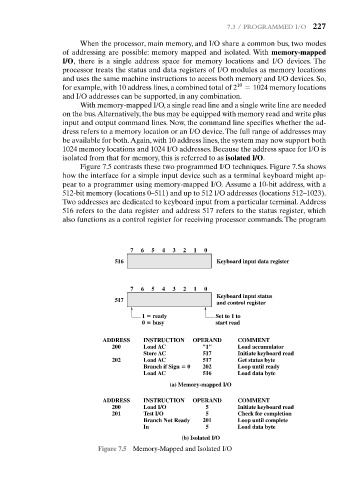
Figure 7.5 contrasts these two programmed I/O techniques. Figure 7.5a shows
how the interface for a simple input device such as a terminal keyboard might ap-
pear to a programmer using memory-mapped I/O. Assume a 10-bit address, with a
512-bit memory (locations 0–511) and up to 512 I/O addresses (locations 512–1023).
Two addresses are dedicated to keyboard input from a particular terminal.Address
516 refers to the data register and address 517 refers to the status register, which
also functions as a control register for receiving processor commands. The program
7 6 5 4 3 2 1 0
516 Keyboard input data register
7 6 5 4 3 2 1 0
Keyboard input status
517
and control register
1 ready Set to 1 to
0 busy start read
ADDRESS INSTRUCTION OPERAND COMMENT
200 Load AC "1" Load accumulator
Store AC 517 Initiate keyboard read
202 Load AC 517 Get status byte
Branch if Sign 0 202 Loop until ready
Load AC 516 Load data byte
(a) Memory-mapped I/O
ADDRESS INSTRUCTION OPERAND COMMENT
200 Load I/O 5 Initiate keyboard read
201 Test I/O 5 Check for completion
Branch Not Ready 201 Loop until complete
In 5 Load data byte
(b) Isolated I/O
Figure 7.5 Memory-Mapped and Isolated I/O