
Page 99 -
P. 99
74 CHAPTER 3 / A TOP-LEVEL VIEW OF COMPUTER FUNCTION
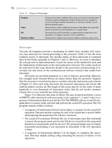
Table 3.1 Classes of Interrupts
Program Generated by some condition that occurs as a result of an instruction
execution, such as arithmetic overflow, division by zero, attempt to
execute an illegal machine instruction, or reference outside a user’s
allowed memory space.
Timer Generated by a timer within the processor.This allows the operating
system to perform certain functions on a regular basis.
I/O Generated by an I/O controller, to signal normal completion of an
operation or to signal a variety of error conditions.
Hardware failure Generated by a failure such as power failure or memory parity error.
Interrupts
Virtually all computers provide a mechanism by which other modules (I/O, mem-
ory) may interrupt the normal processing of the processor. Table 3.1 lists the most
common classes of interrupts. The specific nature of these interrupts is examined
later in this book, especially in Chapters 7 and 12. However, we need to introduce
the concept now to understand more clearly the nature of the instruction cycle and
the implications of interrupts on the interconnection structure.The reader need not
be concerned at this stage about the details of the generation and processing of in-
terrupts, but only focus on the communication between modules that results from
interrupts.
Interrupts are provided primarily as a way to improve processing efficiency.
For example, most external devices are much slower than the processor. Suppose
that the processor is transferring data to a printer using the instruction cycle scheme
of Figure 3.3. After each write operation, the processor must pause and remain idle
until the printer catches up. The length of this pause may be on the order of many
hundreds or even thousands of instruction cycles that do not involve memory.
Clearly, this is a very wasteful use of the processor.
Figure 3.7a illustrates this state of affairs. The user program performs a series
of WRITE calls interleaved with processing. Code segments 1, 2, and 3 refer to se-
quences of instructions that do not involve I/O.The WRITE calls are to an I/O pro-
gram that is a system utility and that will perform the actual I/O operation.The I/O
program consists of three sections:
• A sequence of instructions, labeled 4 in the figure, to prepare for the actual I/O
operation.This may include copying the data to be output into a special buffer
and preparing the parameters for a device command.
• The actual I/O command. Without the use of interrupts, once this command
is issued, the program must wait for the I/O device to perform the requested
function (or periodically poll the device).The program might wait by simply
repeatedly performing a test operation to determine if the I/O operation
is done.
• A sequence of instructions, labeled 5 in the figure, to complete the opera-
tion. This may include setting a flag indicating the success or failure of the
operation.