
Page 37 -
P. 37
Section 1.1 Image Formation 5
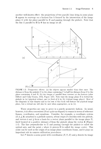
another well-known effect: the projections of two parallel lines lying in some plane
Φ appear to converge on a horizon line h formed by the intersection of the image
plane Π with the plane parallel to Φ and passing through the pinhole. Note that
the line L parallel to Π in Φ has no image at all.
B
C a
O
b
c
A
Π
(a) d d d
Π
h O
Φ L
(b)
FIGURE 1.3: Perspective effects: (a) far objects appear smaller than close ones: The
distance d from the pinhole O to the plane containing C is half the distance from O to the
plane containing A and B; (b) the images of parallel lines intersect at the horizon (after
Hilbert and Cohn-Vossen, 1952, Figure 127). Note that the image plane Π is behind the
pinhole in (a) (physical retina), and in front of it in (b) (virtual image plane). Most of
the diagrams in this chapter and in the rest of this book will feature the physical image
plane, but a virtual one will also be used when appropriate, as in (b).
These properties are easy to prove in a purely geometric fashion. As usual,
however, it is often convenient (if not quite as elegant) to reason in terms of reference
frames, coordinates, and equations. Consider, for example, a coordinate system
(O, i, j, k) attached to a pinhole camera, whose origin O coincides with the pinhole,
and vectors i and j form a basis for a vector plane parallel to the image plane Π,
itself located at a positive distance d from the pinhole along the vector k (Figure
1.4). The line perpendicular to Π and passing through the pinhole is called the
optical axis, and the point c where it pierces Π is called the image center. This
point can be used as the origin of an image plane coordinate frame, and it plays an
important role in camera calibration procedures.
Let P denote a scene point with coordinates (X, Y, Z)and p denote its image